http://www.blazelabs.com/e-exp10.asp
Click for larger view.
| Disk Motor | |||||||||||||||||||||||||||||||||
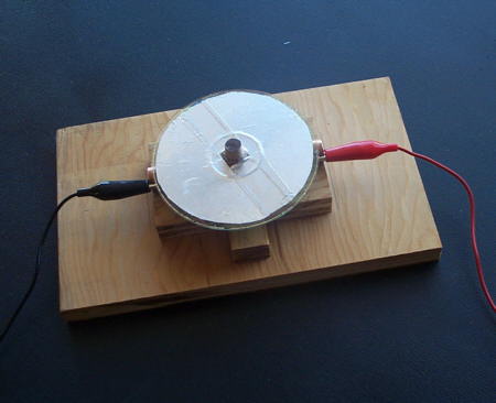
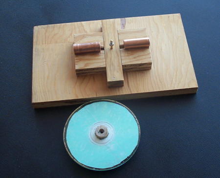
| The disk motor is my favorite. It doesn't do anything but turn around and around, it is petite, and it is simple. The first picture shows the assembled motor, and the second shows the two components of the motor. For a nice discussion of disk motors, see: http://www.blazelabs.com/e-exp10.asp |
|||||||||||||||||||||||||||||||||
|
|||||||||||||||||||||||||||||||||
|
|||||||||||||||||||||||||||||||||
| Disk motor. Click on picture for larger view. | Disk motor components. Click for larger view. |
||||||||||||||||||||||||||||||||
| The rotor consists of nothing more than a blank CDROM, with its label removed and replaced with a coating of aluminum tape. Note that the tape-covered side becomes the top of the rotor. I shaped a piece of dowel to fit through the hole in the disk. I left a flange on the bottom of the dowel to support the bottom side of the disk. The dowel has a central hole in its bottom, in which is set a 5/16 OD by 5/32 ID ball bearing race. The disk sits on a short piece of 5/32 inch diameter brass rod - you can see a second bearing on this rod in the components picture. This two-bearing support assures that the disk will not wobble. The stators are short sections of 1/2 inch ID copper pipe, the same pipe that was used in Dirod #8. As with any of the pipe segments, the ends of the stators were smoothed off to minimize coronal discharge. The stators are now connected to Dirod with two chains, instead of the clip leads shown in the picture. | |||||||||||||||||||||||||||||||||
| The motor will start running within moments after starting to turn Dirod. It quickly accelerates to a rotation rate of about 500 rpm. The Blazelab site mentioned at the top of the page gives a good explanation of how the disk motor works, which is summarized on the Interpretations - Part 3 page. I think that all of the motors I have built can be understood in the same way. | |||||||||||||||||||||||||||||||||
| Home | Dirod #8 | Electrostatic Motors | Motor Modifications | ||||||||||||||||||||||||||||||
| Disk Motor | |||||||||||||||||||||||||||||||||
| Adding A Motor To Dirod | Interpretations | ||||||||||||||||||||||||||||||||
| Interpretations - Part 2 | Interpretations - Part 3 | ||||||||||||||||||||||||||||||||