|
|
|
|
|
|
|
|
|
|
|
|
|
|
|
|
|
|
|
|
|
|
|
|
|
|
|
|
|
|
|
|
|
|
|
|
|
|
|
|
|
|
|
|
|
|
|
|
|
|
Motor Modifications |
|
|
|
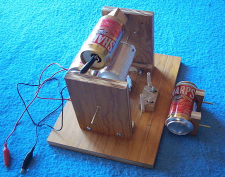
The stators are on opposite sides of the rotor in the first motor I built. Is that really necessary in order for the motor to run? The answer is decidedly "No". For example, the motor shown in the picture below runs well. |
|
|
|
Note that the two stators are quite close together, with a spacing between them of only 1/2 inch. The spacing from each stator to the rotor is about 1/8 inch. Yet the motor still runs at a good speed. The end board construction of the motor is good for this type of experimentation. The upper stator is glued to a block of wood, which has a bolt that passes through the back board. The bolt is slightly off center in the block, so that rotating the stator adjusts its distance from the rotor. |
|
|
 |
|
|
|
|
|
Motor with adjustable stator on top. Click for larger view |
|
|
|
|
|
|
In the picture, another stator is lying next to the base plate. This stator mounts in the two pivoting plastic tubes on the base plate of the motor. Using the pivoting stator, I found that it was strongly attracted to the rotor before the motor self-started. This is an important clue to the initial state of the motor, which is discussed on the Interpretations 3 page. |
|
|
|
Plate Stators |
|
|
|
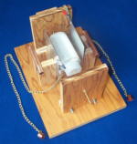
I was curious about what other stator configurations would also work. I had a 4 x 10 inch aluminum sheet which I cut in half to give 4 x 5 inch plates. I mounted these on my test blocks, and positioned them next to the rotor, as shown in the photograph. |
|
|
|
 |
|
|
|
When the plates are placed with about 1/8 inch separation from the rotor, the motor will self-start and run. Note that chains are being used to connect Dirod to the plates. The chains are more efficient than the test lead connections I used initially. It seems that the center of the plate should be at the same height as the axle of the rotor for best operation. |
|
|
|
|
Two plate stators. Click on image for larger view. |
|
|
|
|
|
|
Other Configurations |
|
|
|
On the larger view of the above picture, you will see copper pipe stators on the opposite side of the plate mounting blocks. You can set up the motor so that the pipe stators are close to the rotor. In this configuration, the operation of the motor is problematical. Some times it will run, other times not. This raises the question of how large the stators have to be. The motor runs well if one stator is a plate, and the other is a pipe stator. |
|
|
|
A Note On Rotors |
|
|
|
The basic construction of the rotor is a plastic cylinder (Nalgen wide-mouthed bottle) covered with a layer of aluminum foil, and then an outer layer of a dielectric. I used a sheet of styrene in my first rotor. Later, I built a rotor covered with two layers of plastic sheet (polyethelene?). This rotor seems to be "more efficient" than the styrene rotor, in the sense that it will rotate faster. It might be interesting to search for the "best" rotor. |
|
|
|
Home |
|
Dirod #8 |
|
|
|
|
Electrostatic Motors |
|
Motor Modifications |
|
|
|
|
|
|
Disk Motor |
|
|
|
|
|
|
|
|
|
|
|
|
|
Adding A Motor To Dirod |
|
|
|
Interpretations |
|
Interpretations Part 2 |
|
|
|
|
|
Interpretations Part 3 |
|
|
|
|
|
|
|