
![]()
|
|
From this connector you can control some feature for camera....
1. At pin 1 and 2 is connected On / Off switch. You can turn On/Off by single switch for each camera, or by general power supply relay from Controller at Power Unit, all depends on your own design. I used for this project, relay contact from Power Unit Controller.
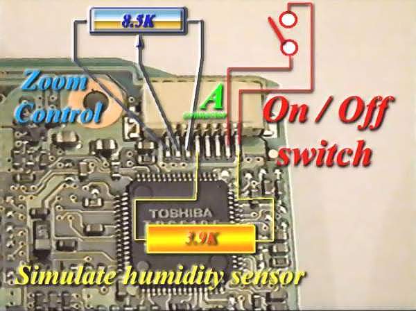 |
2. Between pin 1 and 5 should be connected one 3.9 K ohm resistor. This one will simulate normal position for humidity sensor ( Usually in case of high humidity level, video camera will stop for preventing mechanical damage. But for this project, humidity detector no need anymore, because mechanical system is removed).
Value for this resistor should be near to 3.9 K ohm, otherwise camera will get stop command... No matter if value is higher or lower than 3.9 K ohm ± 10%.
3. Between pin 6, 7 and 8 should be connected one 8.5 Kohm potentiometer. This one will control Zoom feature for camera. There is possible to use one potentiometer for each camera or a special electronic switch from Controller....
Schematic for this electronic switch you can see in following picture :
 |
In this picture is marked the joint points between A connector and 6,7,8 pins ...
This electronic device used 4066 C-MOS switch to simulate potentiometer by two mechanical switches used for ZOOM IN and OUT from Power Unit Controller.
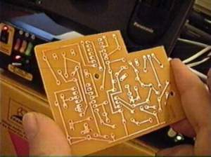
Next is a variant for Pan & Tilt and Zoom electronic switches PCBoard, which is fixed in each camera.....
|
|
| Return
to : |
|
|
|
|
|
|