Fibre Optic trees have become very popular, as they have many benefits compared to traditional Christmas trees. No need to fuss with untangling last year's Christmas lights, it comes complete with its own lights. The tree comes ready to use and is ideal for any indoor room, just plug it in and watch it glow. The fibre optic tree is ideal for my project as it provides great commercial value. The fibre�s allow the light sources to be hidden and therefore more aesthetically pleasing when using a cheap light source.
There are many varieties of fibre optic Christmas trees, varying in colour and size. There are also varying types of light sources however whatever type of light source the tree will light up due to the fibre optics. This will allow a choice of light sources to use on the project, for example bulbs and LED�S.
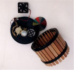
The fibre optic trees on the market use a halogen bulb light source. This shines through a rotating disk that acts as a filter varying the colour of the light. The fibre optic cables are collected at the bottom of the tree at one end. The light shines through the bottom of the fibre optics and travels through the cables due to refection inside the tubes. The cables are spread throughout the tree creating a colourful and festive look.
|
 |
 |
|
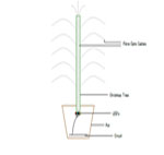
| Left diagram shows inside the pot of a typical fibre optic tree. Right diagram shows fibre optic tree using LED light source. |
|
| Looking at components: |
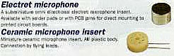
| Looking at inputs for the circuit a microphone will be required. Using rapid electronics catalogue two suitable microphones were found. The most suitable input is the Electret microphone. The component is cheaper and also has PCB pins for ease of connection. |
|
 |
|
| Microphone | Frequency |
Impedance (Ohms) | Standard Voltage |
Sensitivity | Price � |
| Electret | 50Hz to 12KHz |
300 | 4.5 v |
-60 �3 dB | 0.85 |
| Ceramic Insert | 200Hz to 7KHz |
8 | - |
-70 �4 dB | 0.66 |
|
|
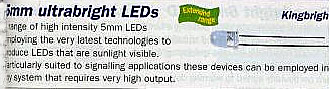
| Looking at output components the cheapest and more effective output would be an LED compared to a bulb. The bulb uses more voltage and also is less efficient than an LED. There are many types of LED�s. However to light the tree very bright LED�s are required.
The LED�s come in a variety of colours with high intensity of light. The colours selected include, blue, yellow, red, white and green. The blue and white LED�s are relatively new technology therefore are slightly more expensive and less bright. However they are still cheaper and more efficient than other light sources. The table below shows numerical details of the LED�S
|
|
 |
|
| Colour | Luminosity | Viewing Angle |
Maximum Current | Maximum Voltage | Price � |
| Orange Clear | 10000 mcd | 20� | 30 mA | 2.8 v | 0.27 |
| Yellow Clear | 2100 mcd | 20� | 30 mA | 2.8 v | 0.27 |
| Bright Green Clear | 4500 mcd | 20� | 30 mA | 4.5 v | 1.15 |
| Blue Clear | 1000 mcd | 16� | 30 mA | 4.2 v | 0.99 |
| White Clear | 3200 mcd | 20� | 30 mA | 4.0 v | 0.95 |
|
|
| Looking at circuits: |
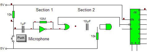
| Using an electronics education magazine I found the above circuit. The full circuit was designed to control lights on and off by clapping. This design idea allows me to develop my own design for my project. Section 1 shows how the person has used logic to convert the analogue signal to digital. A better way of converting the signal would be to use a Schmitt trigger. Section 2 is a monostable extending the pulse time created from section 1 so it can activate the counter. Using a 555 timer monostable would reduce the cost as the number of chips used would be reduced. The design continued allowing the counter to control a logic system to turn the lights on and off of different objects. However I want the counter to control a system that changes different light sequences for the fibre optic tree. To do this I shall use a counter and a pic. The pic will allow to program different light sequences, which should fit the design brief.
|
|
 |
|
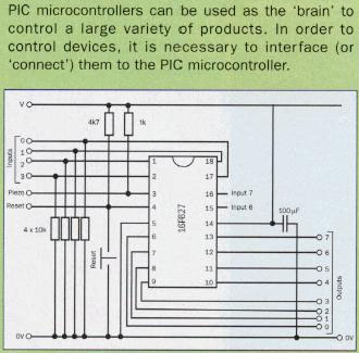
| A process will be needed to control the light sequences. The ideal method would be using a pic. A pic is programmable therefore different light sequences can be created using it. This could be used as a sub-system. Controlled by the counter different light sequences could be activated. The picture on the left shows a pic with the schematics for the necessary interface.
|
|
 |
|
| Contents | Research |
System Designs |
Design Specification |
Input Sub-System |
Process Sub-System |
Output Sub-System |
Final Circuit Design |
Evaluation |
The Project |
