| Specification: |
|
| The output system should respond to the signals generated by the process therefore creating an effective and colourful display. The outputs need to be suitable for the fibre optic tree and therefore be discrete in appearance.
|
|
| First Design: |
|
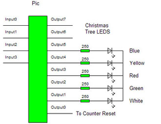
| The fibre optic cables run throughout the tree and converge at the bottom. Therefore a light source placed at the bottom of tree would shine through the optical cable due to its internal reflection. A low power light source would be advantageous increasing the battery life. Therefore the best light source would be light emitting diodes. To produce best results ultra bright LED�s will be used. The LED�s will be connected to the outputs of the pic. The diagram below shows the LED�s connected to the pic with appropriated resistance values. |
|
 |
|
| Second Design: |
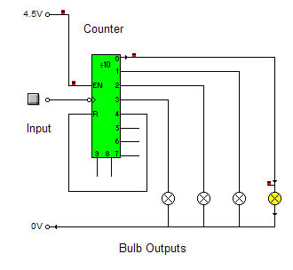
| An alternative design would be to use bulbs as an output. The circuit could be used to control different coloured bulbs which can be bought from rapid electronics. They could be connected to the outputs of the counter therefore controlled by the number of claps.
|
|
 |
|
| Design Choice: |
|
| Using LED�s is a much more efficient use of power. Using bulbs would use more power therefore decrease battery life. The LED�s would make use of the pic and produce a more effective visual display.
|
|
| Testing: |
|
| To ensure the LED�S were working they were tested on a separate test board. They were then connected to the pic. The program was then activated so the output system could be tested by visual checking the LED�s working. Previously the output pins of the pic were tested using a logic probe to ensure they were working however a multimeter was used to find the voltage of each output pin. This allowed the calculation of an appropriate resistance value for the LED�s. The outputs are working fully therefore completing the circuit fully. The LED�s were placed at the bottom a fibre optic tree to test whether they would be bright enough to light up the tree. The LED�s brightly lit up the tree through the fibre optics.
|
|
| Contents |
Research |
System Designs |
Design Specification |
Input Sub-System |
Process Sub-System | Output Sub-System
Final Circuit Design |
Evaluation |
The Project. |
