| Specification: |
|
| The process should register the input signal and therefore control different light sequences. It should be able to create a number of sequences responding to how many claps have occurred in a certain time span.
|
|
| Alternative Design: |
|
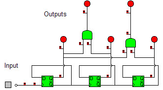
| Using the input system it can control different light sequences using logic. The use of three flip flops will count the number of claps and therefore control, which light is on. An idea for the circuit is shown below.
|
|
 |
|
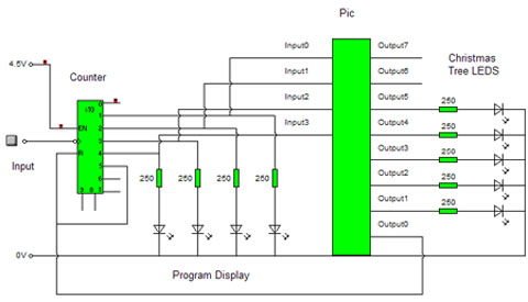
| However this circuit is unnecessarily complicated when a pic can be used that will control the outputs with a simple program. The pic will also allow the LED�s to flash in different sequences at different speeds allowing a more aesthetically pleasing product.
|
|
| Final Design: |
|
| Using a counter the number of claps can be counted from the input of the microphone system. The counter outputs shall be connected to the inputs of the pic. The pic then shall be programmed to produces four different light sequences, as shown on the following page. There shall only be four light sequences due to the limited number of input pins on the pic and the limited number of lines on the pic program. However a larger pic would increase the number of inputs but there is still the limited number of lines on the pic program. The pic shall be programmed using chip factory software and then downloaded to the pic via a serial port. The outputs of the pic will then control the output system of LED�s. One output shall be taken to reset the counter after a certain time, which is shown on the following program. This enables the person to clap the exact number to determine the program number.
|
|
 |
|
Chip Factory Program
Title: Fibre Optic Christmas Tree
Written by:	Adrian Townsend
PIC Type: 	PIC16F84a

00				high	1	Key:
01				wait	020	Output 0: Reset For Counter
02				low	1	Output 1: Blue Led
03				high	2	Output 2: Yellow Led
04				wait	020	Output 3: Red Led
05				low	2	Output 4: Green Led
06				high	3	Output 5: White Led
07				wait	020
08				low	3
09				high	4
10				wait	020	Light Sequence 2
11				low	4
12				high	5
13				wait	020
14				low	5
15	if 0	on		goto	84	Input check at the end of
16	if 2	on		goto	21	each sequence to either
17	if 3	on		goto	48	carry on with same sequence
18				high	0	or move to a different one.
19				low	0
20				goto	00
21				high	5	Light Sequence 3
22				wait	010
23				low	5
24				high	3
25				wait	020
26				low	3
27				high	2
28				wait	010
29				low	2
30				high	1
31				wait	020
32				low	1
33				high	4
34				wait	010
35				low	4
36				high	5
37				wait	020
38				low	5
39				high	1
40				wait	010
41				low	1
42	if 0	on		goto	84
43	if 1	on		goto	00
44	if 3	on		goto	48
45				high	0	Resets Counter using output 0
46				low	0
47				goto	21
48				high	1	Light Sequence 4
49				wait	010
50				low	1
51				high	3
52				wait	010
53				low	3
54				high	2
55				wait	010
56				low	2
57				high	4
58				wait	010
59				low	4
60				high	5
61				wait	010
62				low	5
63				high	4
64				wait	010
65				low	4
66				high	3
67				wait	010
68				low	3
69				high	1
70				wait	010
71				low	1
72				high	2
73				wait	010
74				low	2
75				high	1
76				wait	010
77				low	1
78	if 0	on		goto	84
79	if 1	on		goto	00
80	if 2	on		goto	21
81				high	0
82				low	0
83				goto	48	Light Sequence 1
84				high	1
85				wait	030
86				low	1
87				high	5
88				wait	040
89				low	5
90				high	3
91				wait	030
92				low	3
93	if 1	on		goto	00
94	if 2	on		goto	21
95	if 3	on		goto	48
96				high	0
97				low	0
98				goto	84
99
|
| Reasons For Choice: |
|
| The second design was chosen, as it was simpler to design and produced a better end result. The pic allowed the ability to make flashing and continuously changing light sequences. The first design only allowed the change of the outputs, which was not aesthetically pleasing.
|
|
| Testing: |
|
| The counter and pic were built separately to the input source therefore allowing the use of a push switch to test the process. The input pin on the counter was connected to the push switch. If the input was taken from the input system and any problems occurred this meant the input system would also have to be checked. To test if the counter was working a logic probe was used to test if the pins were high or low according to the count.
The pic was tested on the chip factory program and on a test board before inserting on the circuit. The pic was positioned and LED�s were added to the outputs to visually check the full circuit was working. However one problem was found. When the counter and pic were fully set-up the counter was not resetting properly. Using a multimeter it was found that when the counter reached the forth count it would not reset itself, as there was not enough voltage reaching the reset pin. An attempt to solve the problem was using a transistor to increase the voltage however this only increased the voltage fractionally. More complicated attempts of a logic system would solve the problem however a simple solution of placing a push switch to the reset allows one to manually reset the counter. The problem is not severe as the pic resets the counter after a short time period therefore the manual reset is not entirely necessary but improves the practicality of the circuit.
|
|
| Contents |
Research |
System Designs |
Design Specification |
Input Sub-System | Process Sub-System |
Output Sub-System |
Final Circuit Design |
Evaluation |
The Project. |
