|
| Specification: |
| The system should use an input from a suitable component and ensure the signal can be interpreted by a later process to control different light sequences.
|
|
| Design 1: |
|
 |
|
| Using Electronics Education magazine I created my first design idea for the input. The above design uses a capacitor and an amplifying CMOS NOT gate to interpret the input of the microphone and allow it to be registered by a monostable. This extends the pulse so it can be used later on.
However I have found that this circuit has an alternative design. The monostable above can made using a 555 timer instead of using logic gates. This has the advantage of using one small chip rather than different logic chips for each gate. The input of the microphone is an analogue signal and a Schmitt trigger would be ideal way of converting the signal to a digital pulse. This would be advantageous over the above design, as it would use a 741 chip rather than a larger logic gate chip for one NOT gate.
|
|
| Design 2: |
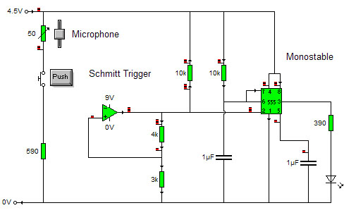
| My second design uses a Schmitt trigger to convert the analogue signal of the microphone to a digital output. This can then be used as input for the light process, however the signal needs to be extended using a monostable. Without the signal being extended the later process would not register the input. The monostable must have a set time period, which is under 1 second . When using a cmos 555 timer for a monostable the calculation of (1.1RC) 1.1*Resistance*Capacitance applies. Therefore a 10k resistor and 1�f capacitor will be required for an appropriate time delay. The circuit below shows how the arrangement is setup and suitable values for the components. This is my chosen design, as it is easy to make.
|
|
 |
|
| Testing: |
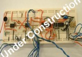
| An LED has been added as a visual output to test whether the circuit works. First the microphone needed to be calibrated by using a variable resistor in the place of the 590 resistor on the diagram. When an appropriate resistance was found, allowing the LED to respond to claps, it was measured using an ohm meter giving a value of 590 ohms.
Using an oscilloscope the voltage levels could be checked throughout the circuit. Also using a logic probe to find out whether each pin on the chips were high or low. However when making the circuit practically it was found that pin 5 on the chip needed to be taken high and pin 4 taken low. This disagreed with text book designs of monostable however it produces the desired outputs. The results showed that when the microphone picks a sharp sound like a clap the Schmitt trigger converts the signal to digital and the monostable extends the pulse lighting the LED.
|
|
| Contents |
Research |
System Designs |
Design Specification | Input Sub-System |
Process Sub-System |
Output Sub-System |
Final Circuit Design |
Evaluation |
The Project. |
|
|
