chapter 7
Modeling the m2 tidal flow in great bay
In this chapter, the M2 tidal flow in the Great Bay and Little Bay section is explored. The Great Bay system, defined by the gbes16 mesh, is forced with the M2 tidal elevation time series predicted in Chapter 6. The simulation parameters are shown in Table 7-1. A space-variable bottom friction coefficient Cd that decreases with increasing depth is used (see simulation C in chapter 6). The relationship between the bottom friction coefficient and depth is given in equation 7.1.
Cd=A-B´h (7.1)
In the above equation, A=1´10-2 and B=1.97´10-4 for the 0m < h < 18.47m depth range for the M2 tidal forcing.
Table 7-1. Simulation parameters for ADAM model in Great Bay.
|
Description |
Parameters |
|
Bathymetry range |
|
|
Porous layer thickness |
h0 = 1.00m |
|
Hydraulic conductivity |
k = 0.0003162 |
|
Bottom friction coefficient |
Simulation C |
|
Time increment |
|
|
Time steps per tidal period |
300 |
|
Tidal periodicity |
T = 12.42 hrs |
|
Length of simulation |
|
|
Numerical implicity |
|
|
Number of nonlinear iterations |
4 |
1.1. Results for the M2 Tidal Forcing without Eelgrass
The system established a dynamic equilibrium rapidly and mass conservation is maintained after the third tidal cycle after a ramp up. Figure 7-1 shows the time history of the total fluid volume across the open boundary transect.
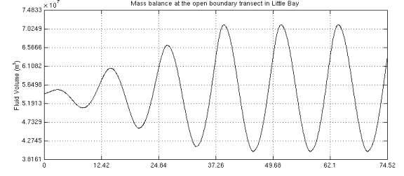
Figure 7-1. Time series of the total fluid volume across the
open boundary transect in Little Bay. The total volume includes the 1.0m deep
porous medium.
The water surface of Great Bay (gbes16 mesh) covers 19.02km2 (corresponding to 9676 elements in the gbes16 mesh) at mean high water and 10.63km2 (corresponding to 4892 elements in the gbes16 mesh) at mean low water. Thus, 44% of surface area in Great Bay drains at low M2 tide. The high water and low water boundaries for M2 tide are shown in Figure 7-2.
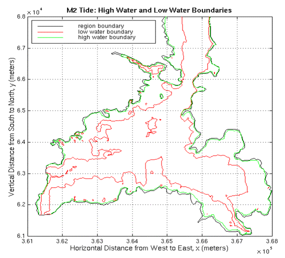
Figure 7-2. High water and low water boundaries for the M2 tide. The high water boundary is shown in green and the low water boundary is shown in red.
The calculated average depth is 2.62m for mean high water and 1.97m for mean low water. Those results show that ADAM model is capable of treating the wetting/drying process in the Great Bay section of the estuary.
The model results at specified stations are compared with the tidal analysis predicted time series. Figure 7-3 shows the comparison of surface elevation and cross-section averaged velocity values at stations T-UNH, T-19 and C-131. The model predicted surface elevation time series at station T-UNH and station T-19 and cross-section averaged velocity time series at station C-131 compare well with the tidal analysis predicted data at those locations for the M2 tidal forcing. The statistical analysis of those comparisons is given in Table 7-2. The details of statistical analysis methods can be found in Chapter 6.
Table 7-2. Statistical analysis results for M2
forcing in Great Bay.
|
|
Station T-UNH |
Station T-19 |
Station C-131 |
|
Correlation Coef. |
1.00 |
1.00 |
0.97 |
|
Skill |
0.99 |
0.99 |
0.90 |
|
RMSN |
0.08 |
0.12 |
0.31 |
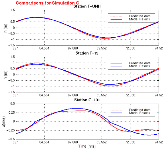
Figure 7-3. M2
forcing: Comparison of model predicted time series and tidal analysis predicted
data at stations T-UNH, T-19 and C-131. Top figure shows the comparison of surface elevation at station T-UNH. Second
figure shows the comparison of surface elevation at station T-19. The bottom
figure shows the comparison of cross-section averaged velocity at station
C-131.
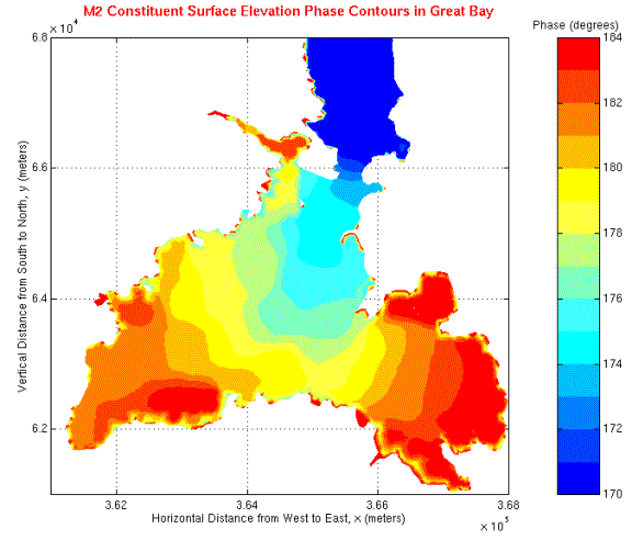
Figure 7-4 shows the surface elevation amplitude distribution in Great Bay. The M2 surface elevation amplitude changes between 0.85m in the channels and 0.75m in the regions close to the shoreline. The M2 surface elevation phase distribution in Great Bay is shown in Figure 7-5. The M2 surface elevation phase increases 10o between the open boundary in Little Bay and the station T-19. This phase difference corresponds to a lag of 20 minutes between the two locations.
The change in phase is consistent with the value given in Swift and Brown (1983). However, the model-predicted surface elevation amplitude does not increase from station T-UNH to station T-19 as given in Swift and Brown (1983).
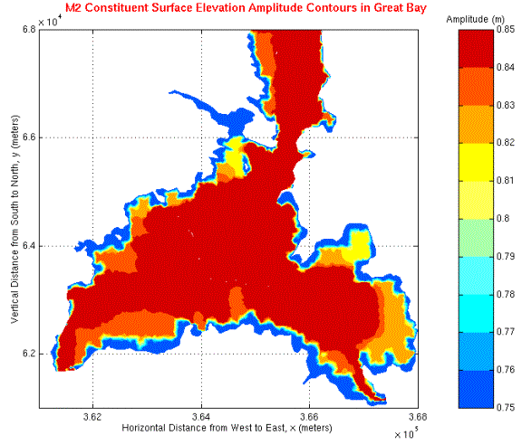
Figure 7-4.
The M2 tide surface elevation amplitude
distribution in Great Bay. The amplitudes are in meters.
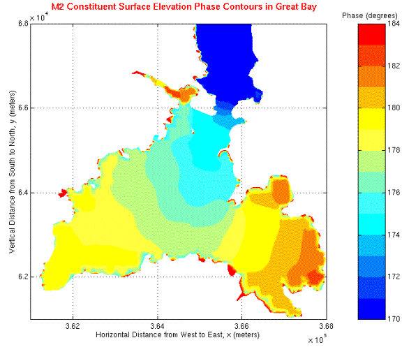
Figure 7-5. The M2 tide surface elevation phase distribution in Great
Bay. The phases are in Greenwich epoch.
The highest velocities are observed in the Furber Strait, where the cross-sectional area of the channel is the minimum. The highest velocity value in the Furber Strait is 1.29m/s for the maximum ebb stage and 1.35m/s for the maximum flood stage. The velocities decrease to 0.4m/s - 0.5 m/s in the channels in south–east and south-west Great Bay.
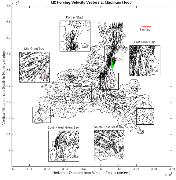
Figure 7-6. Model predicted maximum flood velocities in Great Bay for the M2 tidal forcing . The zoom windows show some important areas. The highest velocity vector is shown in green.
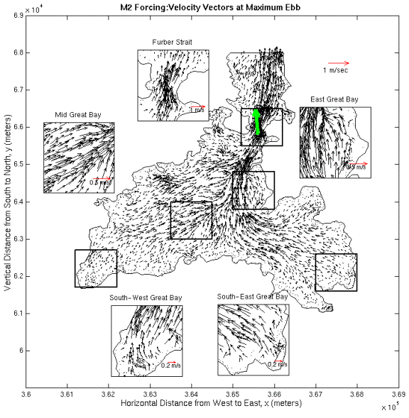
Figure
7-7. Model predicted maximum ebb velocities
in Great Bay for the M2 tidal forcing. The zoom windows show
some important areas. The highest velocity vector is shown in green.
In the Great Bay section of the estuary the deep channels are surrounded by tidal flats and there is a transition from ebb dominance in the channels to flood dominance in the shallow tidal flats. The model results show the transition perfectly. This transition is shown in Figure 7-8.
In overall system, the average depth is the shallowest around high water. As the friction is inversely proportional to the depth, there is more frictional loss at high tide than at low tide in the channels. High friction slows down the propagation of high tide in the channels. The low tide propagates faster than the high tide in the channels, giving way to ebb dominance in those regions. On the other hand, the average depths on the tidal flats are the shallowest around low water. High tide propagates faster than the low tide on the tidal flats making the tidal flats locally flood-dominant areas.
Residual velocities are the time averaged velocities over one tidal cycle. In Figure 7-8, in windows #1 and #2, the ebb-dominant residual velocities in the channels are shown. Window #4 is an example to the flood-dominance on the tidal flats. In windows #3 and #5, once again a flood dominance on the tidal flats and ebb-dominance in the channels are observed. Those two insets are also interesting because of the large-scale gyres, which are generated due to the exchange between the flood dominant and ebb dominant sections.
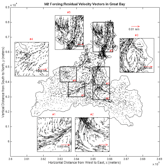
Figure 7-8. Residual velocities in Great Bay
for the M2 tidal forcing. Ebb dominance in the channels is
shown in windows #1 and #2. Flood dominance on the tidal flats is shown in
window #4. Windows #3 and #5 show the gyres which are generated by the exchange
between ebb dominant and flood dominant sections.
1.2. Eelgrass Effects on the M2 Tidal Flow in Great Bay
In this section, the 1990 eelgrass distribution data in Great Bay, shown in Figure 7-9 is used. The eelgrass distribution data is obtained through personal communications with Fred Short from UNH Jackson Estuarine Laboratory.
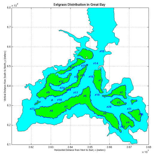
Figure 7-9. Map of eelgrass distribution in Great Bay, 1990. Eelgrass is shown in
green, with the selected stations numbered from 1-27 for sampling hydrodynamic
results from the model.
The bottom friction coefficient distribution found for M2 tidal forcing in the previous sections is used with an adjustment at the eelgrass beds. Eelgrass blocks the water flow, thus eelgrass beds are treated as extra dampers. The bottom friction coefficient values are increased over the eelgrass beds to a value of 0.1, which is 10 times higher than the maximum bottom friction coefficient value used in the previous sections. This value is later checked through personal communications with Blaine Kopp from Maine Maritime Academy who has done a flume tank experiment on eelgrass and found some bottom friction coefficient values for various eelgrass densities. Twenty-seven (27) stations are selected in Great Bay to observe the frictional effects of eelgrass on the tidal flow. Those control stations are shown in Figure 7-9.
The surface area for the mean high water and the mean low water is calculated again for the simulation with eelgrass. The water surface of Great Bay (gbes16 mesh) covers 19.02km2 (9675 elements in the gbes16 mesh) at mean high water and 12.20km2 (55780 elements in the gbes16 mesh) at mean low water. The calculated average depth is 2.62m for mean high water and 1.73m for mean low water. The average depth at mean low water with eelgrass is 24cm lower than the average depth at mean low water without any eelgrass. Also the surface area at mean low water with eelgrass is 1.57km2 (688 elements in the gbes16 mesh) larger than the surface area at mean low water without eelgrass. No significant change is observed in the surface area and the average depth values at mean high water. Those results show that, due to the high friction values, eelgrass holds water at low water and keeps greater surface area wet.
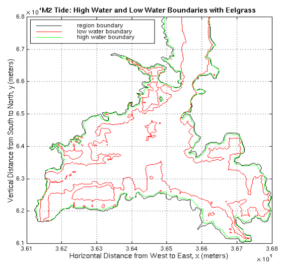
Figure 7-10. High water and low water boundaries for the M2 tide with eelgrass. The high water boundary is shown in green and the low water boundary is shown in red.
The eelgrass distribution affects the surface elevation phase about 2o (see Figure 7-12) corresponding to a 4 min lag on the big tidal flats in south-east and south-west Great Bay. However, the change in the total tidal volume due to the friction effects of eelgrass is negligible (0.5%).
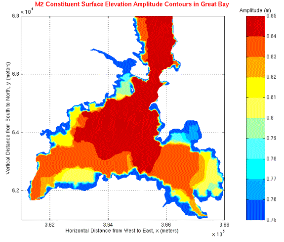
Figure 7-11. M2 tide surface elevation amplitude
distribution in Great Bay with eelgrass. The amplitudes are in meters.
Figure
7-12. The M2 tide
surface elevation phase distribution in Great Bay with eelgrass. The phases are
in Greenwich epoch.
The velocities are damped over the eelgrass beds due to the friction effects of eelgrass. The flow over the tidal flats is directed into the deep channels and the velocities in those deep channels are increased. Those changes are shown Figures 7-13 through 7-15 for the selected sites in Great Bay over one tidal cycle of the simulations.
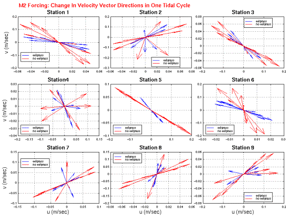
Figure 7-13. M2 Forcing: Comparison between the model-predicted velocity vectors with eelgrass and the model-predicted velocity vectors without eelgrass at stations 1-9. Eelgrass simulation results are shown with blue vectors.
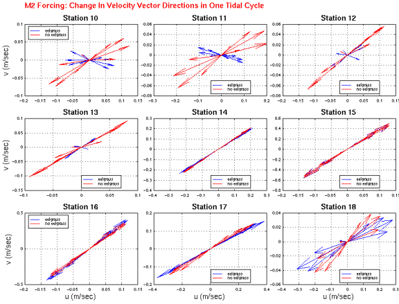
Figure 7-14. M2 Forcing: Comparison between the model-predicted velocity vectors with eelgrass and the model-predicted velocity vectors without eelgrass at stations 10-18. Eelgrass simulation results are shown with blue vectors.
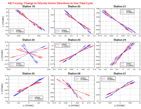
Figure 7-15. M2 Forcing: Comparison between the model-predicted velocity vectors with eelgrass and the model-predicted velocity vectors without eelgrass at stations 19-27. Eelgrass simulation results are shown with blue vectors.
The velocity vectors were examined at the maximum ebb and maximum flood stages with and without eelgrass. The difference observed in velocity magnitudes and directions on the tidal flats and the deep channels are shown in Figure 7-16 through Figure 7-18. The velocity distribution at maximum ebb on a tidal flat in east Great Bay is shown in Figure 7-16. The velocities are slowed down over the tidal flats when there is eelgrass. Also, there is a visible change in the direction of the flow over the tidal flat. On the other hand, the velocities are increased in the deep channel next to the tidal flat.
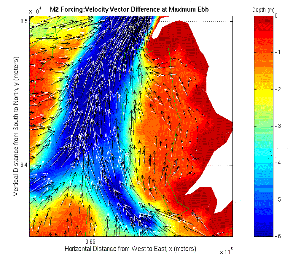
Figure 7-16. M2 Forcing: Difference in current vectors at maximum ebb in east
Great Bay. Velocities without eelgrass distribution are shown with black
vectors. White vectors indicate the velocities when there is eelgrass. The eelgrass bed is surrounded by a green contour.
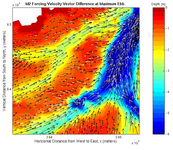
The velocity distribution in south Great Bay is shown in Figure 7-17. There are channels on both the east and the west side of the tidal flat. The velocity vectors on the tidal flat are decreased and directed towards the nearest channel when there is eelgrass. On the other hand, the velocities in the channels are increased.
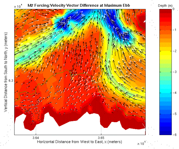
Figure 7-17. M2 Forcing: Difference in current vectors at maximum ebb in
south Great Bay. Velocities without eelgrass distribution are shown with black
vectors. White vectors indicate the velocities when there is eelgrass. The eelgrass bed is surrounded by a green contour.
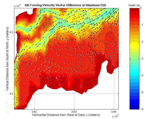
The velocity distribution in mid Great Bay is shown in Figure 7-18. There is a smaller channel on the west side of the main channel. The velocity vectors on the tidal flat in between the two channels are directed towards the deepest channel. When there is eelgrass, the velocity values over the eelgrass bed are decreased while the velocity values in the channels are increased.
Figure
7-18. M2 Forcing: Difference in current vectors at maximum ebb in mid
Great Bay. Velocities without eelgrass distribution are shown with black
vectors. White vectors indicate the velocities when there is eelgrass. The
eelgrass bed is surrounded by a green contour.
The velocity distribution in southwest Great Bay is shown in Figure 7-19. The velocity vectors on the tidal flat outside the eelgrass bed are directed around the eelgrass bed towards the deep channel in the west. When there is eelgrass, the velocity values over the eelgrass bed are decreased while the velocity vectors are increased in the channels.
Figure
7-19. M2 Forcing: Difference in current vectors at maximum ebb in
southeast Great Bay. Velocities without eelgrass distribution are shown with
black vectors. White vectors indicate the velocities when there is eelgrass.
The eelgrass bed is surrounded by a green contour.
Eelgrass, due to the high bottom friction values, decreases the velocities and holds the water for a longer time increasing the pressure gradient. The increase in the pressure gradient causes the water to flow from the tidal flats to the channels, thus the velocities in the channels are increased.

![[back]](../images/home.gif)