Project
Inject
Dave's Modifications Site
gives a guide to the DIY conversion of Blue/Black Holden motors
to Black motor EFI
Page 4
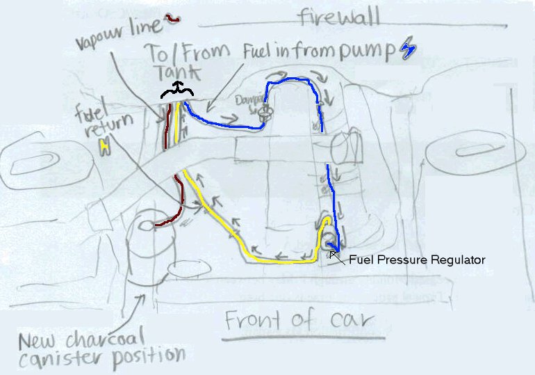
The fuel lines were arranged in this project as follows (iirc):
-
The fuel line that originally went to the input of the carby's fuel filter, before the mechanical fuel pump was bent around slightly to be used as the pipe to the charcoal canister (in the canister's new position.)
-
The fuel line that originally went to the charcoal canister (in the canister's old location was bent slightly, and a fuel line connected this pipe to the return line's pipe.
-
A fuel line from a VL commodore was used for the third fuel line. This line connected the output of the fuel pump (after the fuel damper and filter) to the engine bay's fuel damper (on the same bracket as the Auxiliary Air Valve.) The output of the engine bay's fuel damper goes to the input of the fuel rail (the one closest to the firewall.)
The following sections are coming:
[modifications]
- Air box intake snorkel modification
- Larger injectors
- Different AFMs and associated issues
[component values]
- Coolant Temperature Sensor
- Airflow Meter
- Auxiliary Air Valve
- Electronic Ignition
- Throttle Position Sensor
[pinouts]
[odds and ends,
substitutions etc]
Note: If you have Air Conditioning,
get the version of the VK EFI throttle body that has the idle
compensation solenoid installed. Those without EFI have no
hole for the solenoid and no thread to screw one in.
It is possible to silver solder
(or attach by other means) a return line to a carb tank (tank must be completely evacuated of fuel
first!) but this is not as effective. The VL tank has an
internal swirl pot for the return line so that it can feed the
pump during fuel fluctuations whilst driving.
[faq]
[advantages and disadvantages]
page 1 |
page
2 | page
3 | page
4 | 
 The weeded-out
engine harness is shown on the left. The harness entered
the cabin beside the disabled Air Conditioning block.
The weeded-out
engine harness is shown on the left. The harness entered
the cabin beside the disabled Air Conditioning block.
 Mounting the
computer...
Mounting the
computer...