Re-wiring your truck dash from scratch is fun!
The instrument cluster on our truck was in sorry condition
when we got it. Only two of the five gauges worked, oil pressure and volts. I
started to repair the original gauges and found while the original design was
very efficient for mass production it left much to be desired when it came to
repairs. I set out to redo the entire dash from scratch rather then attempt to
repair the original Mylar film mess.
What GM gave me to work with
The factory harness has one 18 wire connector coming
from the fuse block to the instrument panel. The connector is two sided numbered 1 thru
9 on one side and 10 thru 18 on the other. On my particular truck this is how each wire
on the connector broke down. Most other trucks of this body style
(1973 to 1987) should be similar.
- Light Green > Hi-Beam 12v
- Grey > Panel Illumination 12v with dimmer control.
- Black > Volt Meter Ground
- Pink > Volt Meter 12v
- Pink > Water Temp and Parking Brake 12v
- (2) Brown w/White Stripe > Parking Brake Light Ground
- (2) Brown > No connection on my panel but loops over to wire 18 Fuel
Gauge Signal
- Dark Green > Water Temp Signal
- Black > Turn Signal, Panel Illumination, Water Temp and Hi-Beam Ground
- Light Blue > Left Turn Signal 12v
- Dark Blue > Right Turn Signal 12v
- Pink > 4WD Lock Light, Oil Low Light, Brake Fluid Low Light and Fuel Gauge
12v
- No wire on my connector > Should be to the a switch on the transfer
case for the 4WD Lock light
- No wire on my connector > Should be to the a Low Oil light switch in
the oil pan
- Black > Fasten Belt light and buzzer Ground
- Pink w/White Stripe > Fasten Belt light and buzzer 12v
- Brown w/White Stripe > Low Brake Fluid light sensor
- Brown > Fuel Gauge Signal Where this wire really goes is a
mystery to me. My fuel system had four wires going back to the tanks from
the switch on the dash. Brown, Green, Blue and Brown w/White Stripe. The
Green wire applied power to the tank switching solenoid when the switch on
the dash was activated. The Blue wire was the signal wire for the drivers
side tank. The Brown w/White Stripe wire was the signal wire for the
passenger tank. The Brown wire goes to the passenger side and abruptly
terminates, nowhere? Since the tank switch on the dash had a brown wire
hooked to the center post and the fuel gauge appeared to get its signal from
a brown wire I assumed this was the wire. This was incorrect as this brown
wire hooked to the switch only went right back to the passenger side tank to
oblivion. I do not know where wire 18 goes as I was able to make the fuel
gauges function properly without it. I simply ran a wire from the
center post of the switch to the gauge, works like a charm.
Update 11/19/01 The #18 Mystery wire is the gauge signal. I've seen two dual
tank trucks and both had the wire just hanging back by the passenger side tank.
Both also had another brown wire coming out of the fire wall and crossing over
to the passenger side frame rail. Both were burned right through by the exhaust.
I ran the brown wire on the passenger tank back up to the firewall and attached
it in a safer place by the fuse box. Works as advertised.
NOTE: All the solid pink wires go back to a common pink that leads to the
fuse box. All the black wires go to a common wire that leads to a ground on the
drivers side inner fender. All the gray wires lead back to the dimmer on the
headlight switch. This means you can combine each group with no ill effects.
GM was able to used the Mylar film to send ground and 12v to many different places on the panel with only
a few incoming wires. This made my job a
little more complex as I had to split one ground or 12v source into as many as 14.
I added three new gauges, a Tachometer, Air Pressure and a Transmission Temp
gauge. The intent was to enhance the factory dash functionality and make it
easier to read and more accurate. All the factory "Idiot Lights" were
kept intact and upgraded to brighter, clearer lamps. The gauges used were the
Autometer Performance series. The Autometer Autogauge was deemed way too plain
and most of the others were just too damn nice to put in this crappy old truck.
The New Panel
I started with deciding what gauges to put in the panel.
- Speedometer (New speedometer cable is required. I used a NAPA one. P/N 615-1606)
- Tachometer
- Oil Pressure
- Water Temperature
- Transmission Temperature (Off roading and towing this will come in
handy.)
- Volt Meter
- Fuel Gauge
- Air Pressure Gauge for the On-Board Air
Once I decided to make the panel leaving 100% of the old panel in the trash
it got much simpler. Measurements were taken and a cardboard mock up was mad to
get the basic shape I wanted. A flat aluminum panel was then cut and mocked up
with all the lights and gauges and test fit in the truck.
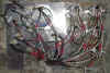
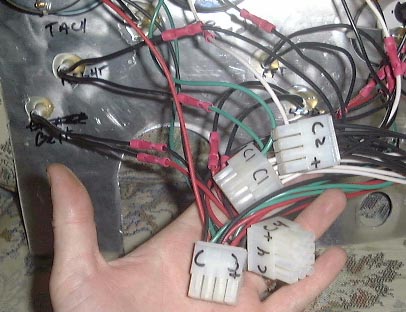
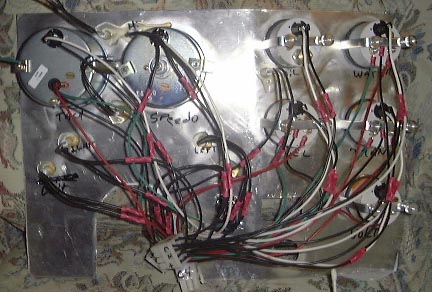
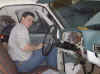
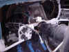
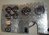
 The two pictures is what the back of the mock up panel looked like once it was all wired up and
ready to test fit. Yes, I'm holding the four Molex style connectors. In the
final panel on the right you can see I got it down to two with use of a power
distribution block
and common ground block. All of the connections were crimped and then soldered. If you
just crimp them they will come loose. Unless you have a better crimper than I
do.
The two pictures is what the back of the mock up panel looked like once it was all wired up and
ready to test fit. Yes, I'm holding the four Molex style connectors. In the
final panel on the right you can see I got it down to two with use of a power
distribution block
and common ground block. All of the connections were crimped and then soldered. If you
just crimp them they will come loose. Unless you have a better crimper than I
do.
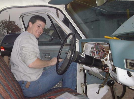
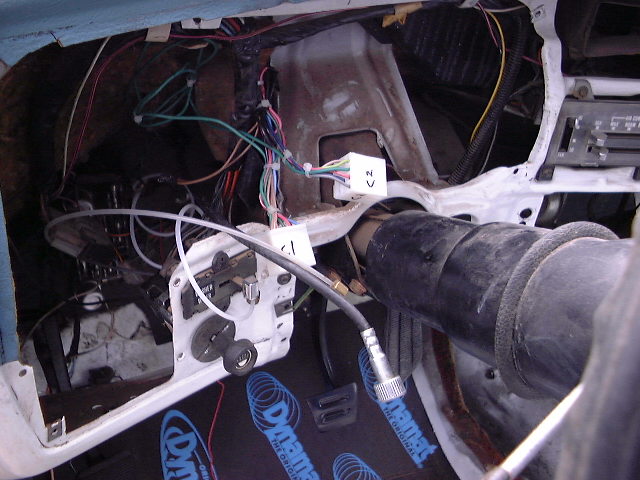
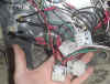
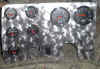
 Here is the prepped dash. Cut off the old connector leaving yourself as much
wire as possible to work with. Crimp and solder all the wires first and then
insert them all at once into the Molex connector and it will
go way faster than doing one at a time. You can see I had to ditch the
drivers side vent and cut one minor chunk of dash out to make it all fit.
Here is the prepped dash. Cut off the old connector leaving yourself as much
wire as possible to work with. Crimp and solder all the wires first and then
insert them all at once into the Molex connector and it will
go way faster than doing one at a time. You can see I had to ditch the
drivers side vent and cut one minor chunk of dash out to make it all fit.
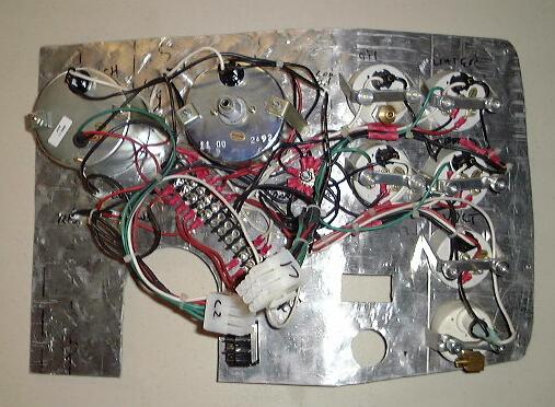
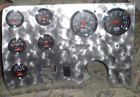
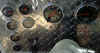
 This is the front of the mock up panel. The gauge holes were initially drilled with 3
½"
and 2 1/8" hole saws. The two empty holes are for the factory wipers and lights. The
column cutout was done with the same 3 ½" hole saw that did the gauges
and it fit perfectly. The light switch was cut with a 1 ½" hole saw. The
wiper cut had to be done with a jigsaw and is a little messy. The gauges were
all positioned incorrectly on this mock up panel except the fuel gauge. Every gauge on the edge of
the panel had to be brought in from 3/4" to 1 ½" inches in order for
the panel to even mount in the truck. When you look at the final you'll see what
I mean.
This is the front of the mock up panel. The gauge holes were initially drilled with 3
½"
and 2 1/8" hole saws. The two empty holes are for the factory wipers and lights. The
column cutout was done with the same 3 ½" hole saw that did the gauges
and it fit perfectly. The light switch was cut with a 1 ½" hole saw. The
wiper cut had to be done with a jigsaw and is a little messy. The gauges were
all positioned incorrectly on this mock up panel except the fuel gauge. Every gauge on the edge of
the panel had to be brought in from 3/4" to 1 ½" inches in order for
the panel to even mount in the truck. When you look at the final you'll see what
I mean.
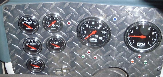
The black switch next to the column cutout is wired to the
old clutch safety switch. It is an illuminated momentary switch that when
pressed engages the starter and flickers the amber light in the switch while the
starter has juice. So to start the truck you turn the key like normal and then
hit the switch. This kind of makes it both a safety and an anti-theft feature. The fuel tank
switch is identical in appearance and has been left in the stock location. It illuminates when
you are on the reserve (Passenger) tank and switches the fuel gauge just like the stock one did.
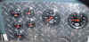
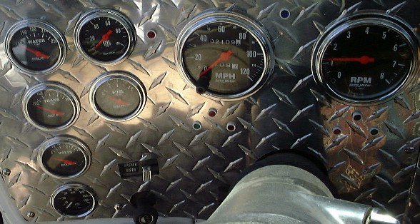
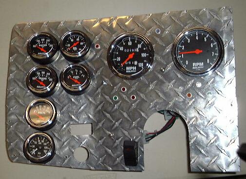
 Here is what the final panel looks like in the truck. From left to right is the
original panel, added air pressure gauge, added angle rings. It's a tremendous improvement from
the stock setup and looks great. There was a problem with the gauges kind of tilting away
from the driver without the angle rings.
Here is what the final panel looks like in the truck. From left to right is the
original panel, added air pressure gauge, added angle rings. It's a tremendous improvement from
the stock setup and looks great. There was a problem with the gauges kind of tilting away
from the driver without the angle rings.
All the final holes were cut with a drill press and a
variable diameter metal hole cutting saw. Everything was almost tight enough to
be a slip fit. If you don't have a drill press Autometer has a place for
you to get the right hole saws. The place is called JL Industries, (800)
521-9520.
- 2 1/16" - HSB-55101-K
- 3 3/8" - HSB-55114-B
I
did not include the AC and radio on the same panel because I wanted to be able to
get at the radio and gauges separately. The radio hole has not been cut in the
panel yet. I'll be able to cut it for a
modern single DIN radio cutout in place of the old factory two knob style
radio.
|