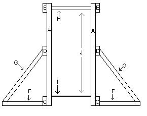
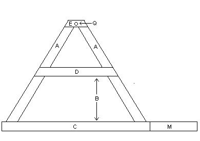
B = 23in. of space beweet base beam and A frame support beam.
C = Base beam, 72in.
D = Mid A frame support beam, 45in.
E = Top A frame support beam, Axle support beam, 10in.
F = A frame support leg base, 24in.
G = A frame support leg, 37in.
H = Axle, 23in., app. 1in. think.
I = Plywood base surface, 96in.X19in., 3 1/2in. hole 14in. from end of base.
J = center of axle hole is 56 1/2in. from base surface.
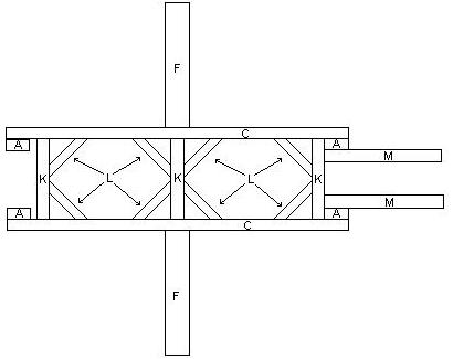
K = Base frame, 22 1/4in.
L = Support beams for base, any length .
M = Base surface extension beams.
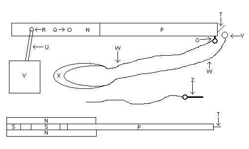
N = Weight baring end of arm, 44in.
O = Eye bolt for release pin.
P = Arm, 71in., has bolt on the end, arm should sit 8in. into weight baring end of arm(N).
Q = Hole for axle. About 34" from the end of the arm.
R = Hole for counter weight chain . About 6" to 8" from the end.
S = Blocks of wood , for extra support, one at 25in. and one 5in.
T = bolt on the end of the arm(P), at a 45 degree angle.
U = Counter weight chain, 25in.
V = Counter weight, the heavier the better.
W = Sling rope, two pieces at 64in. each
X = Sling pocket. piece of clothe, 22in. long, 4in. wide
Y = Sling release ring.
Z = Release Pin