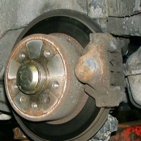
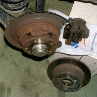
| Rotors can be inspected with the wheel off, but can only be removed
after the caliper has been detached and moved out of the way. If
the pads are being replaced at the same time, they should be removed first
and installed last. Besides rotors, new set screws may be required
because they are often rusted and the torx head can be damaged or stripped
during removal.
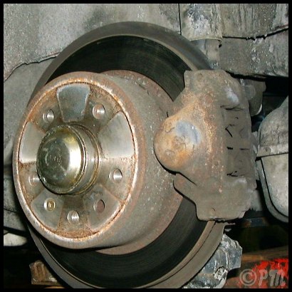
Rear Rotors
|
 |
 |
 |
Brake Line
The brake line runs along the back plate in the same area as the handrake
cable and the wheel sensor electrical cable.
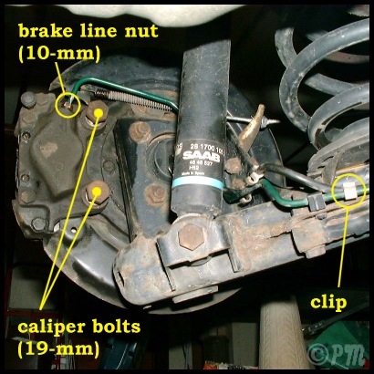
First loosen but do not disconnect the 10-mm brake line union nut.
Use penetrating oil and a flare nut wrench to avoid damage. The brake line
should then be released from the white plastic retaining clip before the
caliper bolts are taken out. |
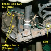 |
Caliper Bolts
The 19-mm (3/4-inch) caliper bolts should be soaked in penetrating
oil one or two days earlier, and again before disassembly. They can take
some effort to break loose, and may require a longer handle than the typical
3/8-drive ratchet. |
 |
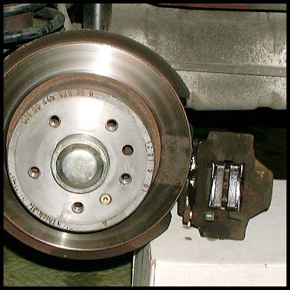
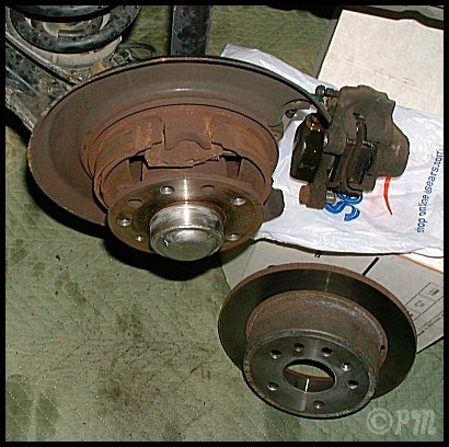
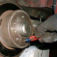
Caliper
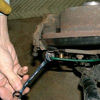
The caliper can be left connected to the brake line to avoid any brake
fluid loss, and just swung out of the way. It has to be supported from
the bottom as shown at left. In that case bleeding the brakes may not be
necessary.
If the caliper is disconnected from the brake line and removed to inspect
the caliper pistons and seals, some brake fluid will be lost, and bleeding
the rear brakes will be required. |
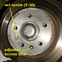 |
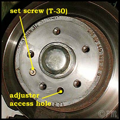
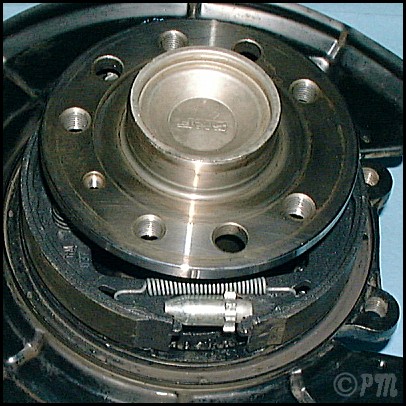
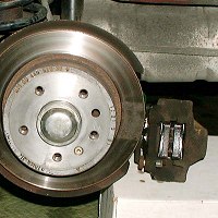
Rotor
With the hand brake released and caliper out of the way, the rotor
is held by one T-30 torx set screw.
Remove the screw, if necessary with the help of more penetrating oil,
and slide the rotor off the wheel hub. If the rotor does not come off easily,
it may be necessary to back off the handbrake adjuster to give the brake
shoes inside some extra room. |
 |
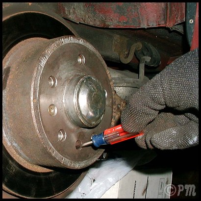
Hand Brake Adjuster
The adjuster can be backed off using a screwdriver or a similar tool
to loosen the handbrake shoes and give the rotor room to slide off the
wheel hub.
Turn the rotor to position the access hole sligtly to the rear of 6
o'clock.. Insert a screwdriver or a similar tool into the access
hole, and rotate the star-shaped wheel one tooth at a time. There is some
resistance as the teeth slide past a spring inside the rotor. |
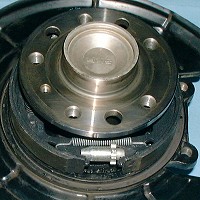 |
To back off the adjuster, turn the wheel down on the left, and up on
the right rear hub.
To tighten the adjuster, turn the wheel up on the left rear wheel, down
on the right. |
 |
Reassembly
Reassemble in reverse order. Clean and apply anti-seize to the face
of the hub, set screw, and face of the rotor being installed. Replace the
set screws if rusted, or if the head was damaged during removal.
Adjust the hand brake shoes to allow the hub to spin freely with the
hand brake released, and to grab on the 5th-6th click of the handbrake
lever. |
Rotor Thickness
10 mm (new)
8 mm (minimum)
References
Saab EPC 5-0150
Haynes Ch 9, section 9
Torque Settings
Caliper bolts, 59 lb-ft
Set screw, 7 lb-ft |
Tools Used
-
3/8-drive ratchet
-
19-mm socket
-
10-mm flare nut wrench
-
T-30 torx bit
-
Torque wrench
-
Wire brush
-
PB Blaster
-
Brake cleaner
-
Anti-seize
|
|