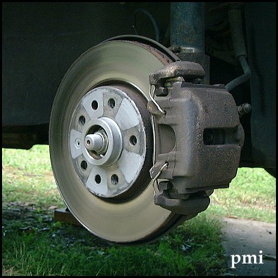
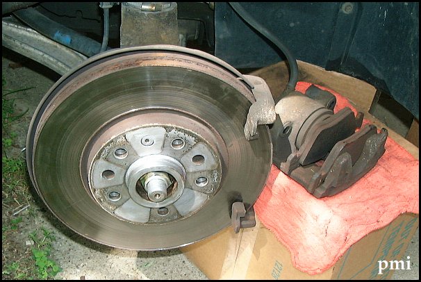
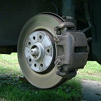
| Front brakes have vented discs with a single-piston floating caliper.
This means the caliper consists of two parts, a bracket which is attached
to the wheel backing plate and does not move, and a "floating" brake pad
housing. The floating part mounts on two guide pins which are attached
to the fixed bracket, and slides back and forth a fraction of an inch as
brakes are applied and released.
Front Pads and Rotors
The floating part of the caliper
has to be removed to get access to the pads, but it can be left attached
to the rubber brake line. If the rotor is worn, it can take extra
effort to remove, because the pads may catch on a ridge which forms on
the edge of the rotor. On reassembly, the retaining springs usually
have to be forced back in place. While inspecting the brakes, note
the shape of the head of the rotor set screw for future use. On early
models it takes a fairly small metric hex bit. |
 |
 |
| Removal |
|
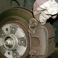 |
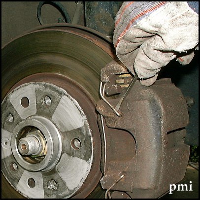
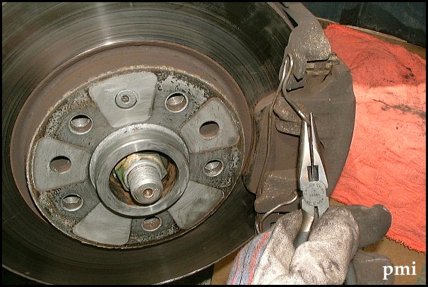
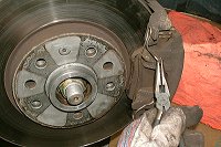
Retaining Spring
The spring is fairly stiff, to keep the outside brake pad firmly in
place. It comes off easily when one end is first pried out of the
retaining hole using a screwdriver or a pair of pliers. Note its position
on the caliper for later, removal is much easier than reassembly. |
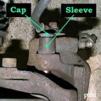 |
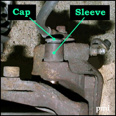
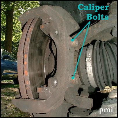
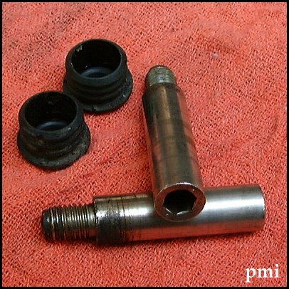
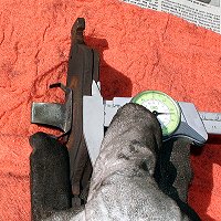
Guide Bolt Sleeve and Caps
The guide bolts are behind the wheel backing plate, as seen from the
top of the wheel at left. When brakes are applied, the caliper piston
pushes on the inside brake pad, and the floating portion of the caliper
slides along the guide bolt to apply pressure to the rotor equally from
both sides. The bolts are inside a rubber sleeve, protected by a dust cap
which has to be removed for access. |
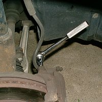 |
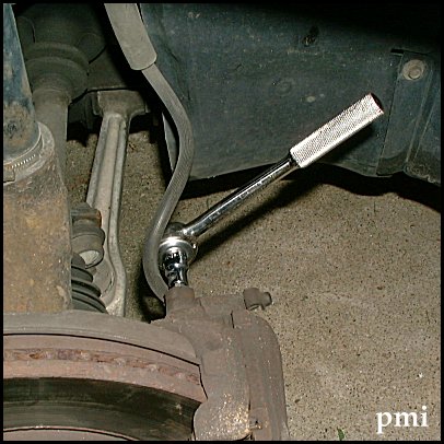
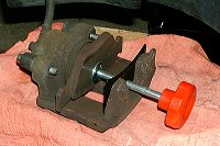
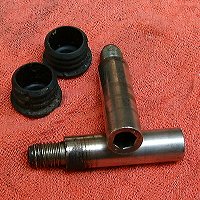
Guide Bolts
The bolts (also called "slide pins") have a 7-mm hex head. They can
be unscrewed using a long allen wrench, or a ratchet with a bit holder
as shown on the left. The bolt fits snugly into the sleeve. After
it has released from the threads in the fixed portion of the caliper, it
has to be removed carefully to avoid damage to the sleeve. |
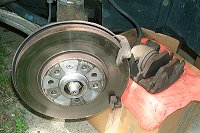 |
Pad Housing
The housing must be loosened by rocking it back and forth before it
can be removed. This pushes the caliper piston and the inside brake
pad back, so it will clear the raised lip on the edge of the rotor and
lifted off . The housing can be left attached to the brake line,
and supported by something like the box shown on the left. |
 |
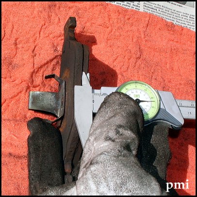
Pads
The outside brake pad is flat and can be pried off easily.. The
inside pad has an attached spring which slides into the caliper piston.
Check the rotors for scoring and uneven wear, and the pads for 5 mm minimum
thickness. Measure the friction material, NOT the entiere pad. Clean the
housing and the pads with a wire brush, and apply some brake grease to
the back of the pads before reinstalling in the housing. |
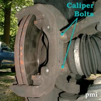 |
Rotors
To remove the rotors, the caliper bracket and main caliper bolts have
to come off. The bolts are tightened to a fairly high torque (78ft-lbs),
and may require some extra leverage to break loose. After removing the
caliper bracket, the rotor is only held by a small set screw. It
is tightened only lightly, but may need penetrating oil if rusted, to avoid
stripping the head. |
| Installation |
|
 |
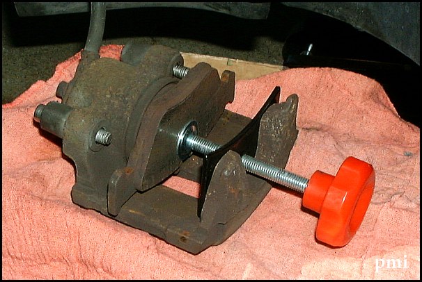
Pads
Insert the inside brake pad into the housing. Push the inside
pad and piston in far enough to make sure it will go over the rotor easily.
If the pad and piston do not move easily, use a C-lamp or a tool available
in any part store to compress the piston. Insert the outside pad,
and replace the housing on the fixed part of the caliper. |
 |
Bolts
Clean the guide bolts with a rag, and if necessary with solvent, and
lubricate the cylindrical portion of the bolt with a rubber-friendly lubricant
or brake grease. Insert the guide bolts into the sleeves, and tighten
to the specified torque, about 20 lb-ft. Fit the caps back in place. |
 |
Spring
Install the spring back on the caliper. One end of the spring
is inserted into its retaining hole first, then the spring is pushed
into position against the brake pad. The second end can be pulled
into place using needle-nose pliers. Make sure the ends are pushed
all the way into the retaining holes. |
 |
Wheels
Stock front brakes shed a lot of abrasive black dust. Normally
it can be cleaned fairly easily using any product like WheelBrite, or household
detergent and a soft brush. If the metallic powder remains on the
wheels too long, it may become permanently embedded in the finish.
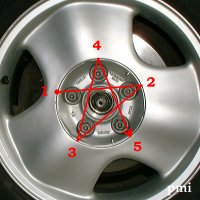
For best results, tighten wheel bolts in a star pattern, on alloy wheels
to 86 ft-lbs. |
Pad Thickness
5 mm (minimum)
Torque Wrench Settings
Guide bolts, 19 lb-ft
(20.5 lb-ft for 1997-'98)
Caliper bolts, 78 lb-ft
(81 lb-ft for 1997-98)
Rotor set screw, 3 lb-ft
Wheel bolts, 86 lb-ft
(74 lb-ft on steel wh.)
|
Tools
-
Needle-nose pliers
-
3/8 drive ratchet
-
5-mm hex bit (set screw)
-
7-mm hex bit (guide bolts)
-
10-mm hex bit (caliper bracket, if removing rotor)
-
Torque wrench (optional)
-
Wire brush
-
Brake grease
-
Anti-Seize
|
References
Saab EPC 5-0120
Haynes Ch 9, section 4 |
Notes
If new pads were installed, bleeding the brakes is recommended.
Brakes on later models are larger and pads have different part numbers
for 1997-98 models. |
|