
PRESSURIZED FLUIDISED BED COMBUSTION (PFBC) TECHNOLOGY FOR POWER GENERATION -- Technology Status
1.0 THE PFBC PROCESS
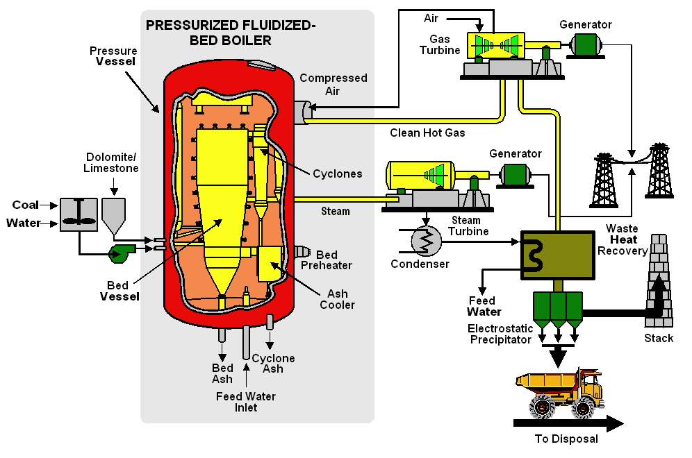
The Pressurized Fluidised Bed Combustion Systems employ a combination of Rankine Cycle and Brayton Cycle with the objective of achieving high cycle efficiency and also lower emissions. The technology is environmentally benign. The process employs a pressurized fluidised boiler which operates at a temperature of around 860 0C, pressure of around 16-18 bars and generates the flue gases at pressure. The fuel is fed along with the sorbent and is maintained in fluidised condition in the pressurized combustion chamber. The sorbent is fed to facilitate capture of sulfur from the coal in the bed itself resulting in consequent low sulfur emission.
The pressurized flue gases are cleaned off all the suspended particulate by means of high efficiency cyclones and are expanded into a gas turbine. This expansion of flue gases in the gas turbine generates power. In addition, the excess air requirements of the boiler are met by the gas turbine compressor. Since the gas turbine also supplies the excess air requirements of the boiler, it sets the limitation on gas turbine output. The excess air requirements are maintained at around 20% and thus the PFBC plant size is determined by the gas turbine sizes available. This also produces a power split between power generated by steam cycle and that generated by gas turbine which is of the order of 80:20.
On the steam cycle side, the fluidised boiler, the heat transfer surfaces are embedded in the fluidised bed and steam generated is passed through the conventional steam cycle operating on Rankine Cycle. Thus a combination of Rankine Cycle & Brayton Cycle results in higher cycle efficiencies which are projected to be higher than conventional steam plants by 4-5%.
PFBC Process Diagram (Tidd, USA):
2.0 ADVANTAGES OF PRESSURISED FLUIDISED BED COMBUSTION TECHNOLOGY
The major advantage of PFBC process is that plant efficiency can be significantly improved by combining Rankine Cycle & Brayton Cycle.
For the first generation PFBC combined cycles, efficiencies approaching 40% and heat rates of about 8500 Btu/kWh can be achieved. Second generation advanced combined cycles are expected to attain efficiencies more than 45% and heat rates as low as 7500 Btu/kWh.
Increasing the process pressures results in several advantages in addition to combined cycle operation and higher combustion rate. The increased pressure and corresponding air/gas density allow much lower fluidising velocities (around 1m/sec) which reduce the risk of erosion for immersed heat transfer tubes. At elevated pressures the heat released within the combustors increases and deeper beds are needed to accommodate the required heat transfer surface. The use of compressors for combustion air takes care of the higher pressure drop across these deep beds. Full load bed depths range from 3.5-4.5 m depending upon pressure.
The combined effect of lower velocity and deeper beds results in greatly increased in-bed residence time which reduces emissions of SOx and thus improves combustion efficiency. In fact, the deeper beds allow 50% of the total residence tome to be in the bed where it is more effective compared to 10-15% in the shallow atmospheric bubbling beds.
| PLANT | Output MWe | Coal Type | SO2 emission % removal | NOx emission mg/MJ |
| Vartan | 135 | Bituminous | 94-99 | 10-50 |
| Tidd | 70 | Bituminous | 91-93 | 75-90 |
| Escatron | 79 | high sulfur black lignite | 90 | 75-90 |
| Wakamatsu | 71 | Bituminous | 90-95 | 15-40 |
Since air mass flow m= VA, the high air/gas density results in much lower required bed plan area. For the same m, a bubbling bed PFBC at 174 psi with a superficial velocity of 3ft/s will require 28% of the bed plan area of an atmospheric fluidised bed.
Because the gas turbine compressor capability sets the requirement of the boiler and major components, PFBC lends itself to a high degree of standardization. The range of PFBC design sizes is set by the compatible gas turbine sizes.
3.0 PFBC PLANT CYCLES
3.1 Combined Cycle
The gas leaving the boiler is cleaned and sent directly into the gas turbine. This produces the gas turbine inlet conditions in the range of 175 to 240 psi at approx. 840 0C. This produces a power split between the gas and steam cycles which results in about 80% generation from steam cycle and 20% generation from gas turbines. The power to the gas turbine is sufficient to drive a compressor to provide the preheated, pressurized air to the Fluidized bed boiler for the combustion process.
3.2 Advanced Combined Cycles
In the case of PFBC, to prevent ash slagging, minimize the formation of thermal NOx, maximizing the sulfur capture and avoid formation of alkalis in the gas stream, the bed operates at about 8600C. This produces the gas turbine entry temperature of around 8300C. To further increase the contribution of the gas turbine in the plant efficiency, the turbine inlet temperature needs to be increased.
Conventional gas turbines operate at upto 10930C inlet temperatures with new designs in the range of 12600C. By increasing the gas output temperature from PFBC, higher output from gas turbines can be produced. The most popular approach is to combine partial gasification with PFBC and use topping cycle. Application of this however, requires hot gas cleaning system to remove particulate from syngas and the gas leaving PFBC before sending to gas turbine. A typical combined cycle configuration is shown in Fig. 2.
4.0 PFBC SYSTEM COMPONENTS
The PFBC systems comprise of the following major components:
4.1 PFBC Gas Turbine Requirements
As the gas turbine is driven by hot pressurized gases from the boiler and simultaneously supply combustion air to boiler and generate electricity, certain characteristics are desirable:
Typically at Tidd Power Station, gas turbine is a two-shaft machine. On one shaft, the variable speed, low-pressure turbine is coupled to low pressure compressor. On the other shaft, the high-pressure turbine drives both the compressor and generator. There is an intercooler between low and high-pressure compressors. The advantage of two-shaft design is that the free spinning low-pressure turbine can accommodate reduced gas temperature and resulting reduction in airflow as load is reduced while maintaining constant speed at generator.
4.2 Fuel Feed System
Fuel feed system is either pneumatic or wet type. Normally coal is fed as coal -water mixture as they have demonstrated to burn more evenly. The optimum system design depends upon ash and sulfur content in coal. For fuels with low ash contents, coal-water mixture has found favours since large quantities of water are needed for coals with high ash, which affects its efficiency. The fuel is fed in the form of coal-water paste with 25% water by weight. This has been typically followed at Tidd. The fuel feed size is lower than 0.75 in.
4.3 Sorbent Feed System
Sorbents are not combustibles and are generally fed either continuously or intermittent. In the latter case, lockhoppers are used. The sorbent is crushed to around 3 mm top size, dries and fed in lock hoppers.
4.4 Gas Cleaning System
Gas cleaning systems have not yet been proven in PFBC systems and present a limitation. Typically the following type of gas cleaning systems are being employed:
5.0 TECHNOLOGY STATUS
The following is the list of major technology suppliers for PFBC.
| S. No. | Technology Supplier | Licensees | Remarks |
| 1. | ABB Carbon AB, Sweden | IHI, Japan | Bubbling Bed |
| 2. | MHI, Japan | ||
| 3. | Hitachi, Japan | ||
| 4. | Ahlstrom Pyropower, Finland | Circulating Bed | |
| 5. | Lurgi Lentjes Babcock, Germany | Bubbling Bed & Circulating Bed |
The PFBC technology is still at demonstration stage worldwide. Only a few plants are being set up in Europe, USA and Japan to demonstrate the technology out of which five are currently in operation. Almost all these plants have come up during the current decade only. The list of various plants based on this technology worldwide is as below:
List of Projects Employing PFBC Technology
| S. No. | NAME/COUNTRY | SIZE MWe | FUEL | COMM. DATE | REMARKS |
| 1. | Vartan, Stockholm, Sweden | 135 (2x P200) | Bituminous Coal | 1990 | ABB-Carbon, Power & Heat |
| 2. | Tidd, AEP, Ohio, USA | 73 | Bituminous Coal | 1991 | Asea-Babcock (ABB-Carbon and B&W Joint Venture) |
| 3. | Escatron, ENDESA, Spain | 79.5 | Black Lignite | Nov,1990 | ABB Carbon, Babcock & Wilcox Espanola, Demonstration plant |
| 4. | Wakamatsu, EPDC, Kyushu, Japan | 71 | Bituminous Coal | Dec,1994 | Demonstration plant supplied by IHI, Licensee of ABB |
| 5. | Tomato-Atsuma, HEPCO, Japan | 85 | Coal | 1995 trial operation | MHI, Japan; began commercial operation in Feb 1998; tubular ceramic filters |
| 6. | Trebovice, Czech Republic | 70 | Hard Coal | 1996 | Power, Steam & Heat |
| 7. | Karita, KyEPCO, Kyushu, Japan | 350 | Hard Coal | 1999 | Under Construction |
| 8. | Osaki, Chugoku, Japan | 250 | 1999 | Hitachi, Under Design Stage | |
| 9. | HKW Cottbus, KFB/SWC, Germany | 71 | Local brown coal | 1999 | ABB Kraftwerke AG, Under Design Stage |
6.0 COSTS
The investment costs of projects based on the PFBC technology are projected to be around $ 1300 to $ 1400 per kW which is around 25-30% higher than the conventional PC based plants. However, these costs may have upward revision to account for various refinements in the technology during the demonstration stage. Once the technology is fully demonstrated, and reaches the maturity stage, the costs may show a downward trend.
Cost of Generation of PFBC compared with other Advanced Technologies
Source :

BACK TO MY HOME PAGE | IGCC | CFBC | PFBC | SOLAR THERMAL | WIND POWER | GEOTHERMAL | FUEL CELLS | COALBED METHANE