


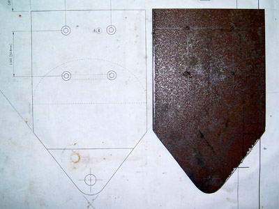
Here are some pics of my steel ankles. I chose steel for strength...I would have preferred to use aluminum, but I do not have the tools required to weld it. The steel ankles will be bolted to the aluminum legs, and held in place with 4 bolts. The bolt heads will be hidden by the curved outer detail. Special thanks go to David Mallory, for printing the blueprints up for me. This would be very difficult without Dave buckley's beautiful blueprints!


The feet were also scratch built from steel. I decided to use 4" scooter wheels for several reasons. First they are cheap and readily available, and second the 4" diameter would allow the wheels to be as far apart as possible, allowing for a more stable robot when in two leg mode.
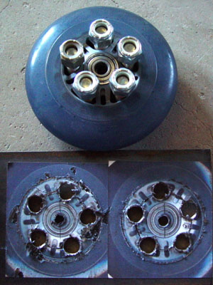

The motor comes from AM Equipment and was originally designed as a light wheelchair motor. A gearbelt pulley was mounted to the motor, and the whole thing assembled.
I am planning on only having two wheel drive for now, just to test that this system will work. The pulley diameters were determined by Dave Painter, whose droid I used as reference for this particular project.


Next work began on the leg rods. These rods are used to keep the legs vertical when R2 is standing in two legged mode. When the transition is made to three legged mode, the rod tilts the foot ever-so-slightly as to keep the foot level with the floor, while allowing the leg and body to tilt.
This design has been adopted by many builders wanting to achieve 2-3-2. Much support and reference material came from Craig Smith, James "Spanky Hodson and Heath MacMillan. The exact measurements for the location of the leg rods came from Heath specifically. His PDF drawing can be viewed by Clicking Here.