![]()
BM Audio Power Amplifier
![]()
Before I begin, I would like to thank the person who helped me on the amplifier, despite his other commitments. He is none other than the designer himself, Bert Molenkamp.
![]()
Over the past year, I have been struggling to get my power amps working. As
you can see, I spent quite a lot of effort on the casework. Note: Pictures have
already been scanned.
![]()
DESCRIPTION
First have a look at the
schematic. It is
fairly straightforward and parts are easily accessible to the amateur
constructor. Here is a close-up and a description of the
circuit board. This is
my first major project and due to my lack of experience, I did a really bad job
out of it. All parts are of the cheapest quality (sad to say) except for the
casework and power supply. For a taste - All carbon resistors 5%; Mospec
(Taiwanese) transistors and; the cheapest capacitors you could find.
Bert Molenkamp,
the designer of the amps says that the power supply is the most important. I
took his advice and spent a large part of my budget on the power supply. It
consists of a medium-sized transformer (Avel Linberg 330VA), and six 12,000uF
Mallory capacitors per monobloc channel. I used 25A bridge rectifiers and a 7824
voltage regulator (for the input stage). If you are curious, here is a picture
and a small description of the
power supply. And here
is a schematic of it.
Wiring was done with 16A electrical wiring (solid core) throughout, more for
aesthetic reasons than anything else.
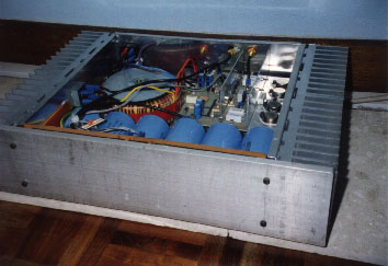
The casework is my pride and joy. In my case, it is the one I spent most time
on (drilling, mounting etc.). Each monobloc consists of four 0.8 C/W heatsinks.
The base is super heavy-duty - it is machined from 6mm aluminum milled with
adequate ventilation holes. The top panel is 3mm sheet aluminum. The rest of the
casework is simply 1.6mm sheet aluminum chosen for easy workability. Although it
doesn't look like a commercial amp, I'd say I did a fairly decent job out of it.
After all, don't most (if not all) DIY amplifiers look like
this?
![]()
PROBLEMS ENCOUNTERED
Constructing the amplifiers was no easy task, even for seasoned constructors. I would classify the circuitry as intermediate. But this was actually the part which took the least time. If you are not particular about quality or brand, searching for parts should not be too difficult, and it should be easily available anywhere. The major "find" for me were the heatsinks and the filter capacitors (Mallory). I had properly estimated the cost to be around US$600, but if you are really interested in building the amps, a stereo one should cost about US$600 total, but for my monobloc version, around US$1000. This figure is not too exaggerating, I assure you. As you read on, you will understand why. Soldering the board was pretty easy, just look out for orientation and short-circuits. When wiring the power supply to the amps, it is safety first.
Though simple enough for amateur constructors, proper wiring ensures that
nothing goes wrong (or explodes!). All switches and sockets should be rated at
least 10A. Although this is an overkill, it will go a long way to protect the
user in case of a fault (common to most DIY amps). I cannot determine a proper
value for the fuses, these should be the smallest value usable (for safety!).
![]()
TESTING
Due to the typical amateurish syndrome, I was extremely impatient to get the
amps up and running. The minimum equipment you need are a good digital
multimeter and proper safety rules. No, I do not have a variac, but I strongly
urge you to get one if you do not already have one. OK, so I plugged in the
amps. I did, however, follow the procedures given by
Bert Molenkamp.
The first time went well with good results (see PERFORMANCE) until thermal
runaway occurred. This is the part I want to warn all fresh amateurs out there -
use the smallest fuses possible, and ALWAYS use an output fuse! (e.g. 1A) A
thermal switch is also a good idea. Impatience on my part led to blowing not
only my output transistors, but also my precious Chario speaker! Worse still,
the amps were plagued with problems thereafter. One channel is working perfectly
right now, with class AB bias current of about 150mA. However, offset is pretty
high (0.1v standby, 0.25v when in use). This causes audible distortions,
especially on high musical peaks. I suspect this has more to do with parts
tolerance than anything else. If anyone has a solution for this, please e-mail
me.
![]()
PERFORMANCE
I would say I was really dumbstruck the first time I listened to the amps. I
used Chario Hyper 1mk2 speakers (5 ohms nominal and not very easy to drive). I
used only 400mA bias, probably only about 10 watts in class A, the rest in class
AB. With a supply voltage of +/-36vdc, I probably got around 60 watts class AB
into 8 ohms. You can change the power output to your needs by varying the supply
voltage. Generally, the sound was clean but never dry. Particularly to note was
the bass. Bert
Molenkamp states his amps at a damping factor of 2000 at 100Hz for an 8 ohm
resistive load. In my version, I would say around 500 (note the lousy parts used
and the relatively small filter capacitors and transformer). This poses no
problem, however. The amps grip the speakers with amazing control and the result
is - music. Detail was good with adequate depth and width of soundstage. If you
ask me, I am amazed how such lousy parts could put out such wonderful sound. In
fact, it sounds similar to the YBA2. Those of you who are interested in building
the amps should get good parts (e.g. Metal film resistors, Motorola transistors,
and of particular note, the right capacitors). I can only guess how good the
amps will sound with such parts. Also, since it is quite a rugged design, high
bias currents can be used (up to 5 Amps). This makes the amps run in full class
A, with even lower crossover distortion and better audible performance. However,
the power supply and heatsinking should be adequate. The construction details
can be obtained from Bert Molenkamp. I am, of course, willing to help anyone if
you would e-mail me, but I am also a beginner, so don't ask me advanced
questions.
Better still, construct the Bride of Zen from Pass Labs (see article).
![]()
ENDING NOTE
At this point, you may like to have the PCB traces and additional
construction notes. But due to a lack of space, I am only making this available
through e-mail. In short, this is a wonderful amp to have if built with patience
and reasonable parts (not like me!). Think about it - if I can do it, so can
you! I have also made a few additions to the amps to make them more stable. Due
to limited space, I cannot put all data on my homepage. If you would like to
know more, do e-mail me. I will be glad to reply.
![]()