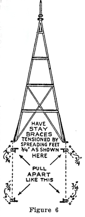
With a pencil or chalk, mark through the holes in the tower feet. Then measure out 3/4" from each hole, as shown in Figure 6, and drill the bolt hole on the new marks.
Before setting the tower, make rubber cushions for the feet. These can be rubber shoe heels, or several thicknesses of old inner tube. Bolt one foot down first with the cushion under it. Then bolt down the leg diagonally across from the 1st one, stretching it out to meet bolt holes. This will assure a solid tower mounting, as it takes all the slack out of the braces. Now fasten the other two legs. Make sure the nuts are held with lock washers or double nuts.
To protect the plant from lightning connect a No.4 copper wire from the tower to a metal rod driven several feet into the ground.
It is a good pan to run the wires from the tower to the instrument panel (203 or 222) before placing the chassis on the main stem.
Choose the correct wire size from the wire size chart--Figure 7.
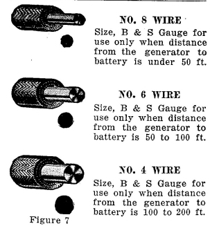
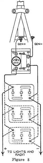
Figure 8 shows how the wires are connected. One wire goes from the positive or insulated terminal on the main stem to the "Gen. +" terminal on the instrument panel and the other goes from the grounded (not insulated) terminal on the main stem to the grounded "Gen.-" on the instrument panel.
It is a good plan to bring the wiring up the inside of the tower. In this way, it can be taped securely to one of the legs and will not spring out to catch the propeller. All outside wiring from tower to the instrument panel should be supported on strain insulators and should be neat and free of kinks. Where the wire enters a building, make a drip loop so the rain will not follow the wire into the wall. This simply means that the wire is bent down and then up again just before it goes into the wall.
The wire from the instrument panel to the batteries should be stranded or flexible insulated copper cable. No. 12 is about the right size though No. 14 will do. If you do not have either of these, use No. 16 twisted lamp cord using both strands for a single lead by twisting the wire together at the ends, where you have taken the covering off. Attach the battery clips to one end of each lead. The clip with the plus sign (+) stamped on it should be connected to the "Bat +" terminal on the instrument panel. The other lead connects to the "Bat -" terminal.
| << Previous Page | Return to Home Page | Next Page >> |