Now clip the positive (+) lead to the positive (+) terminal of the battery and the negative (-) terminal of the battery.
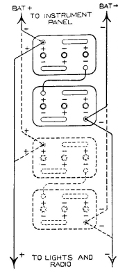
Figure 8 shows the connections for a 6 volt connection.
Twelve volt connections are shown in Figure 9.
The chassis consists of the main frame (C-207), two tail arms (C-129R) and (C-129L), two halves of the tail vane (D-130) and the tail arm spacer (A-128). The positive and negative collector brushes (A-133) and (A-132) are installed in the main frame and the radio condenser (A-100) and the generator cable (A-109) are attached to it.
In the following instructions, we will speak of the right side and left side of the machine. We will also speak of the front and rear. These directions are to be taken as if you were standing behind the tail vane and facing into the wind. The propeller end is the front end. The tail vane is at the rear end. The generator cable will attach to the left side of the generator.
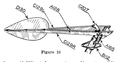
1)-To assemble the chassis, bolt the tail arms (C-129R and C-129L) to the sides of the main frame (C-207). The right hand tail arm has a small loop embossed in the bend, near the front end. Use 5/16"x1/2" bolts with the heads on the inside. Lock washers and nuts go on the outside. Leave these bolts loose for the present. The generator cable clip (A-113) goes under the nut of the rear bolt on the left side.
2)-Insert 5/16"x3/4" bolts through the flanges of the tail arms and the ears of the trunnion pin. The heads should be down. Use lock washers and nuts. Leave these bolts loose until the trunnion pin has been driven in.
3)-The governor spring clip (A-128) comes attached to the governor spring. Slip it between the tail arms and bolt it in place with a 1/4"x1 1/4" bolt, lockwasher and nut.
4)-Bolt the tail vane (D-136) between the tail arms with the wide end in front and the small end to the rear. Use 1/4"x3/4" bolts.
5)-Tighten all bolts except the two in the trunnion pin clamp.
6)-The throwout collar assembly (B-112) has the retriever spring (A-165) attached to it. Slip the throwout collar onto the main frame pipe with the yoke down. Hook the retriever spring (A-165) into the loop in the right tail arm.
7)-Slip the turntable bearing (A-144) in place over the main stem (B-195) on the tower.
8)-Place the rain cup (A-227) over the turntable bearing.
9)-Mount the assembled chassis on the main stem. Make sure the collector arms (A132 and A133) are making good contact with the main stem collector parts.
10)-Place the collector cover (A-225) in place on top of the chassis, aligning the holes in the ears with the hole in the trunnion pin clamp.
11)-Mount the generator, sliding the trunnion pin (A-108) through the generator trunnion, the ears of the collector cover and the trunnion pin clamp. Put cotter keys in the ends of the trunnion pin and draw up the trunnion pin clamp bolts.
12)-Connect up the throwout linkage and governor spring clevis (A-214) to the rear fin of the generator, using clevis pin (A-146), washer and cotter key.
13)-Hook governor spring (A-127) into clevis (A-214).
14)-Bring throwout loop (A-120) up through inside of tower and past the main stem base. Hook it into the holes at the ends of the throwout yoke (B-112).
15)-Check the whole assembly for free movement and make sure no parts are binding.
| << Previous Page | Return to Home Page | Next Page >> |