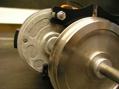
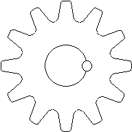
| Probably the most difficult engineering task I found building my Trojan was pinning the metal drive gear onto the motor shafts, so that the gear was fixed onto the shaft and rotated with the motor. As stated in the Ride On Railways instruction manual, this task needs a small pillar drill and a steady hand to hold in place the metal gear, whilst drilling down the side of the motor shaft and the inside of the gear as shown by the small round circle in the diagram on the right. |
| Page last updated on : |
| 29/01/2006 |
| Copyright (c) GALT Locomotives 2006, all rights reserved |
 |
| GALT LOCOMOTIVES The Home of the Little Purple Engine |
| Trojan Assembly |
| The suggested method of pinning the gears in the instruction manual is to drill the holes with a 1.5mm twist drill and then to snap the end that goes in the chuck off in the hole, after applying Nutlock to the hole. Whilst this will work, I did actually try it, I found that where the drill had snapped off, it left a very shape burr that was extremely difficult to file down. Consequently, I used 1.6mm Silver steel instead, as 1.5mm was not available from the metal supplier I used. |
| Suggestions When preparing to drill the hole for the pin, it is very important that the motor shaft, which has been cut down to the correct length, is filled flat to a right angle with the side of the shaft. Also the metal gear must be held very tightly, when beginning to drill the hole, otherwise it will �Chatter� and you will end up drilling a misshaped hole that is a lot larger than you actually want, as I found to my cost !!! |
| Motor Assembly |
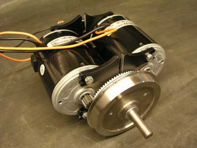
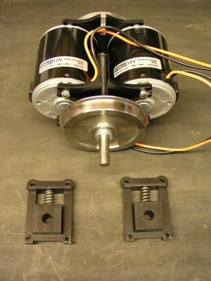
| When cutting the mounting screw threads on the motor to length, it is important to follow the instructions in the Trojan manual, as the clearance between the end of the screw thread and the wheel is approximately 1mm when cut. When installing the motors onto the motor mounts I found it was, to a certain extent, guess work as to the position of the motors on the mounts, to provide optimum gear teeth contact. I found the best motor positioning was when the motor mounts just encroached onto the small recesses on the ends of the motors, as shown in the picture on the right. Unfortunately, by having pressed on wheels, it�s not possible to see the amount of gear teeth contact between the two gears. |
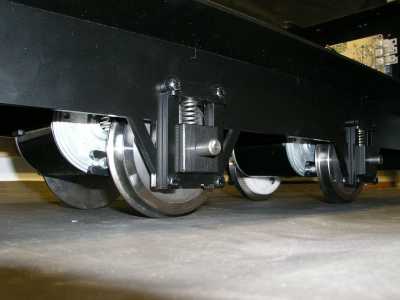
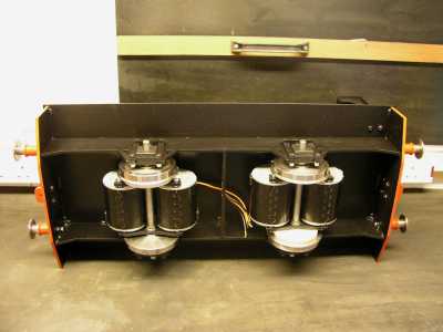
| The two pictures shown below and right are of a pair of motors, fixed onto the motor mounts and assembled onto the axel. The slots on the top of the motor mounts allow the motor assembly to locate onto a chassis cross member, so that the suspension sets, shown at the bottom of the right hand picture, only allow vertical suspension movement. |
| Unfortunately, when I mounted the motor assembly onto the chassis the first time, I heard a grating noise and found that the paint on the inside of the motor mount slots had scraped off. When the slot and chassis cross member are painted, they no longer fit together, due to the thickness of the paint. To overcome this problem and to prevent metal corrosion around the slot, I carefully filled down the inside faces of the slots on all four motor mounts, by approximately 0.5mm. I then re primed and painted the slots which appeared to solve the problem. The two pictures shown below are of the two motor assemblies mounted onto the Trojan chassis. |
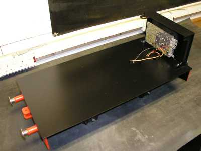
| The picture shown on the right is of the 4QD controller mounted, without the heat sink on the Trojan control panel. The wires appearing through the holes in the chassis are from the rear motor arrangement. I made this temporary installation to see how much room I had to mount the battery frame. |
 |
 |
 |
 |
 |
 |
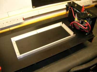 |
| Battery Frame |
| The purpose of the battery frame is to prevent the two batteries from sliding around on the chassis, and in the worst case falling off. I made my battery frame from lengths of aluminium angle, 20x20x3mm thick, although any suitable angle could be used including �Dexian�. Although the positioning and sizes of the angle is dependant on the size of the chosen batteries, I did make oblong holes in the aluminium angle to allow batteries of different sizes to be used at a later date. This flexibility allows battery widths from, in my particular case, 164mm up to 175mm to be used. It also allows the angle brackets to be positioned tight against the sides of the battery bases to help hold them in position. |
 |