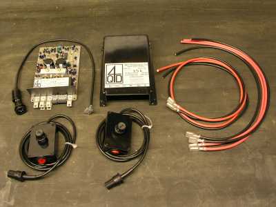
| Pictured on the right is the electronic controller kit supplied by 4QD to specifically work with the Trojan. Although purchased as a complete kit, two additional crimp connectors are required to allow the un-terminated ends of the battery leads to be connected to the battery terminals. Also up to four additional crimp connectors are required to connect the two 12Volt batteries together and, if used, any fusing arrangement. Although not shown in the right hand picture, the kit also includes a 5 LED battery condition meter. |
| Page last updated on : |
| 13/06/2006 |
| Copyright (c) GALT Locomotives 2006, all rights reserved |
 |
| GALT LOCOMOTIVES The Home of the Little Purple Engine |
| Electrical Installation |
 |
| The type of crimp connector needed, really depends on the type of batteries used to power the Trojan. Some batteries may have bolt terminal where as others have studs that have clamp on connectors. The batteries I used, which were sealed lead acid GEL deep cycle ones, had M6 bolt terminal connections. Although I did purchase an additional 1m of both red and black 6mm2 cable for connecting the batteries together and the fusing arrangement, I did find that this was unnecessary, as the 600mm battery leads, were more than long enough to provide the additional cabling to achieve this. |
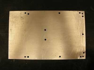
| The Heat Sink |
| Although the controller panel on the Trojan is predrilled to directly accept the 4QD Pro-120 controller, I added an additional aluminium heat sink, in between the heat sink on the 4QD controller and the Trojan control panel. 4QD do actually supply a heat sink for the controller; part number PRO-BAS, however, as I already had a suitable scrap piece of aluminium, which just needed to be cut to size. The handbook for the Pro-120 controller provides the measurement dimensions of the recommended heat sink base, which is also drilled to accept the controller�s plastic cover. When installing the controller onto either the aluminium heat sink or the Trojan controller panel, it is important to use a suitable heat sink compound, which needs to be spread liberally on the top face of the 4QD Pro-120 controller heat sink. |
 |
| Electric Modifications |
| Although the handbook for the Pro-120 controller provides a complete wiring diagram of the connections to the controller it is still difficult to fathom out, when the hand controller and extension lead are considered. To help clarify things I have reproduced the circuit diagram that I followed. For comparative purposes, I have used the same colour scheme as that used by 4QD and Ride On Railways. The thicker red and black wiring is the 6mm2 wire supplied with the Ride On Railways kit from 4QD. |
 |
| Of particular note is the wiring connections to the motor assemblies. If like me, you have a geared drive on both sides of the Trojan chassis, then the wiring connection to one of the motor assemblies needs to be reversed, otherwise you will fine both assemblies rotating in opposite directions and the Trojan standing still !!! For geared drive on both sides of the Trojan chassis the connections �A� and �B�, in the above diagram, needs to be swapped over. |
 |
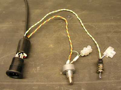
| The above diagram shows the modifications I made to the controller extension lead, all of which are discussed in the Pro-120 controller handbook. The adjustable potentiometer and the 4k7 ohm resistor are used to limit the top end of the Trojan�s speed. This feature is particularly useful if children are likely to be driving the loco. The picture shown on the right is the modified controller extension lead. |
| Suggestions I cut down the potentiometer and cut a screwdriver slot into the end, which can be seen in the centre of the picture shown on the right. This stops �little fingers� interfering and changing the speed adjustment that you have painstakingly added in. |
 |
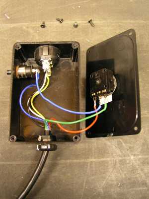
| The modifications to the hand controller to add a �Deadmans� switch is fairly easy as shown in the diagram above and the picture shown on the right. Unfortunately, the switch I chose to use for the Deadmans switch is, as I found out on Lady Galtbe�s first outing, very uncomfortable and difficult to use. In hindsight I should have opted for either a sprung loaded potentiometer arrangement, or a micro switch with a roller on the arm that acts as a Deadmans switch. |
 |
 |
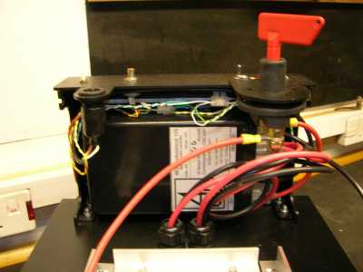 |
| The picture shown on the right is of the 4QD controller and its associated wiring installed on the Trojan control panel. The thicker red and black wiring is the 6mm2 wire supplied with the Ride On Railways kit from 4QD. The multicoloured wire to the left and on top of the 4QD controller integrates the �Ignition Switch�, �Top Speed Adjust� potentiometer and the �Aux� 24volt supply, which is for the battery meter and the �Steam� whistle. The big red �T� switch is the optional battery isolation switch, which I highly recommend and an optional extra. Without it you will not be able to isolate the batteries without disconnecting the wiring. |
| Update Using a micro switch with a roller on the switch arm works really well and in comfortable to use. All I did was to make the existing round hole for the old Deadmans switch, square and slightly larger than the roller on the micro switch. |