| As with any locomotive having some form of horn or whistle is essential when you want to run at your local club or pull ride on coaches with fare paying passengers. With my Trojan saddle tank being electric powered the availability of a steam whistle was rather limited. Consequently, I opted for an electronic version of a steam whistle rather than a horn. My son convinced me that a diesel horn did not suit our saddle tank !!! After much searching I found the Trax Controls steam whistle, which consist of a small PCB containing the electronics and a large 8 ohm speaker. My first problem was that the electronics were designed to be powered from 12volts rather than the available 24volts. Powering the electronics from one of the 12volt batteries was feasible, but would have required a separate On/Off and additional wiring on the circuit breaker, neither of which I was keen on. The only other option was to build/purchase a separate 12volt power supply or PSU, which I could run from 24volts. |
| Page last updated on : |
| 13/06/2006 |
| Copyright (c) GALT Locomotives 2006, all rights reserved |
 |
| GALT LOCOMOTIVES The Home of the Little Purple Engine |
| Installing the Whistle |
| PSU Requirements |
| The first step in this process was to determine how much current the electronics were drawing from a 12volt supply when the whistle was activated. Using my trusted bench power supply I was able to determine that the electronics drew some where between 350 to 450mA, depending on how long the activation button was pressed for. The simplistic approach to building the power supply would be to use a 12volt regulator and powering it from the 24volt battery supply. This approach has a few problems, in that the 12volt regulator would have to dissipate up to 5.4 Watts of power, albeit for only a second or so, due to the current drawn and the voltage difference between the total battery voltage, at least 24volts, and the 12volt regulator. Consequently, the approach I decided to take was to purchase a 6watt 24volt to 12volt DC-DC converter, which although cost considerably more than the 12volt regulator, it did solve the heat dissipation problem and took up less space. |
| The Steam Whistle |
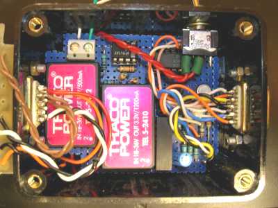
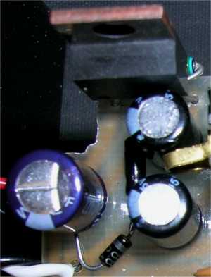
| Trax Controls steam whistle is a similar design to that by R.A. Penfold in his book on Model Railway Projects (BP95), published by Bernard Babani, ISBN 0859340708, with just a few minor component modifications. Despite making a few minor tweaks to the circuit I was not able to improve the whistle volume by a sufficient level to achieve what I was looking for; it sounded more like an �O� gauge loco than a 5� gauge loco. On further examination of the circuit�s operation, I was able to determine that the power amplifier in the circuit was limiting the output drive into the speaker due to the operating supply voltage of 12volts. Although the power amplifier is capable of being supplied by up to 22volts, the electronic steam whistle circuit when driven by any voltage greater than 12volts no longer sounds remotely like a steam whistle, due to the biasing on the transistors. Despite all my efforts the only route left is to either design my own electronic steam whistle, which I�m not that keen on, or modify the transistor biasing in the circuit by R.A. Penfold so that it can operate from 24volts. If I cannot get a suitable power amplifier that operates from 24volts I�ll have to include a 2-3volt drop on the supply rail for the power amplifier. The picture shown below left, is of the 12volt DC-DC converter (right hand side), along with other circuitry, which is used to drive the current meter I installed to monitor the current drain from the batteries. This meter, as I found out on Lady Galtbe�s first outing, was able to indicate when I was attempting to pull a too heavy load. The pictures shown below right, is that of the installed Trax Controls Steam Whistle. I had to cut down the PCB and remove the screw terminal blocks in order to fit it into the box. I also added the heat sink, shown at the bottom of the picture, as during testing the power amplifier became very hot. |
 |
 |
| 24Volt Modified Steam Whistle |
| While testing the steam whistle circuit to determine which components needed to be changed to allow it to run from a 24volt battery supply, I noticed that the steam whistle sound was louder when driven from my trusted bench power supply, than when driven from the 12volt DC-DC converter (Something I had not previously noticed). When the steam whistle was operated, the current drawn from the bench power supply was �Instantaneously� available, whereas the current supplied from the DC-DC converter appeared to be �Slugged� or �Damped�, taking longer to achieve the required current flow. As the whistle was only operated for a short period of time (The duration of the Push button being pressed), the power amplifier was not actually obtaining the current it required to make the whistle of the desired volume, before the button was released. Although I was intending to redesign the entire steam whistle to run of 24volts, it soon became apparent that it was much easier to modify the power amplifier circuitry to run off 20volts and leave the rest of the circuitry running off 12volts. By chance, the power supply track on the PCB was configured such that the power amplifier was fed first and the actual steam whistle circuitry was fed after the power amplifier, via the Whistle Push button that operated it. Consequently, the power amplifier could easily be powered from a 24volt supply, which could in theory be reduced back down to the required 12volts for the steam whistle circuitry. The diagram shown below is a block diagram of the Trax Controls steam whistle. I have deliberately used a block diagram, as to avoid infringing any copyright laws. |
| For simplicity I decided to supply the power amplifier from 20volts, thus giving a 2volt clearance on the amplifiers maximum operating voltage, and supply the rest of the circuit from 12volts. As the 555 timer circuit was not being used, I also removed the 555 IC, black with 8 pins in the middle of the board, from the PCB. By temporarily removing the power amplifier IC, I was able to determine that the steam whistle circuit required approximately 8mA to drive it. Based on this information I used the following items to modify the circuit:- |
 |
| 12volt Zener diode 1.2k ohm � watt resistor (used to provide the bias current for the 12volt Zener diode) 7805 5volt (1A) voltage regulator (Ideally use a 20volt regulator) 15volt Zener diode (Used to convert a 5volt regulator into a 20volt regulator) 510 ohm � watt resistor (Used to convert a 5volt regulator into a 20volt regulator by providing the bias current for the 15volt Zener diode) 100uF 50Volt electrolytic capacitor (Optional) Wire link |
| The diagram shown below is the block diagram of the modified Trax Controls steam whistle, which allows the entire circuit to be powered from a 24volt battery system. The only reason I used a 5volt regulator and a Zener diode is that�s what I had lying around in the electronic draws at the time. |
 |
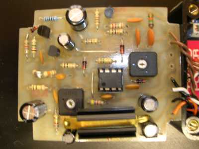
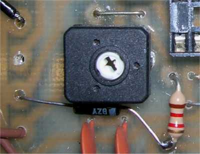
| The picture shown on the left is of the unmodified steam whistle PCB. The three light areas, top left hand corner next to the heat sink, above pitch preset and to the right of the pitch preset, shows the positions of three diodes that need replacing. |
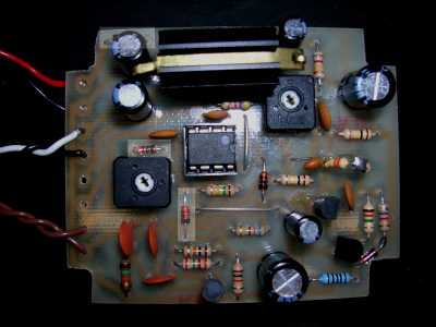
| The right hand picture shows the installed 20volt power supply. The black diode (1N4001) in the top left hand corner of the PCB, is replaced by the voltage regulator, with the regulator input pin going in the PCB hole nearest the supply input and the regulator output pin going in the other hole. The regulator common pin is bent at 90 degrees pointing towards the two capacitors shown on the right of the picture. Soldered between the common pin and the output pin is the 510 ohm bias resistor, one end of which can be just seen in the top right hand corner of the picture. Soldered between the common pin and the 0volt supply input is the 15volt zener diode, with the bar or cathode end of the Zener connected to the common pin. The optional 100uF electrolytic capacitor is soldered between the supply input pads to the PCB. Please note the polarisation of the electrolytic capacitor. |
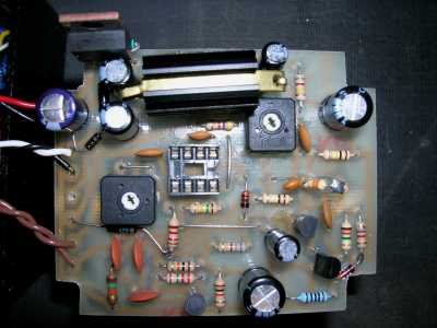
| The picture shown on the right is of the fully modified steam whistle PCB, with the 555 timer IC removed. Although not an ideal solution, this modification did significantly increase the volume of the Steam Whistle, albeit not by as much as I would have liked, but then again I�m comparing the volume from a real steam whistle against and electronic one. |
| The left hand picture shows the installed 12volt power supply. The two red signal diodes, which were above and to the right of the pitch preset have been removed and replaced with a wire link and a 1.2k ohm bias resistor. Soldered between the bias resistor and the 0volt supply input is the 12volt zener diode, with the bar or cathode end of the Zener connected to the resistor. |
| Suggestions By using a 16volt or 17volt Zener diode it is possible to increase the power amplifier supply voltage to 21 or 22 volts, however, this will be using the amplifier at its maximum ratings. Alternative voltage regulators can be used but any changes would have to be matched by changes in the Zener diode voltage to maintain the supply voltage to the power amplifier of at least 20volts. An alternative solution would be to used a LM317 adjustable voltage regulator, which, with the use of two resistors, could be used to obtain an exact voltage without the need for the voltage regulator Zener diode. |
 |
 |
 |
 |