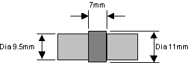
| To ensure the drill holes for the crank pins were parallel to each other and at right angles to the length of the crank, I turned up the simple rod arrangement shown in the diagram on the right. The central part of the rod was the same diameter as the axle hole in the crank, approximately 11mm. The ends of the rod were turned down to be the same size as the crank pin, approximately 9.5mm. With the rod in the axle hole and the crank pin in the crank pin hole, the assembly when placed in a vice, with the rod and pin resting on the vice jaws, the crank is correctly positioned to obtain parallel drill holes. |
| Before I came to install the running gear according to the Trojan instruction manual, I heard thought the �Graph vine� that someone had experienced problems with the running gear working loose while running. I spoke to Paul Middleton from Ride On Railways about this and he suggested the following changes to the standard Trojan installation, which is primarily based on that found in the Trojan instruction manual. |
| Page last updated on : |
| 25/06/2006 |
| Copyright (c) GALT Locomotives 2006, all rights reserved |
 |
| GALT LOCOMOTIVES The Home of the Little Purple Engine |
| Installing the Running Gear |
 |
 |
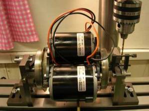
| To ensure that the cranks were at 90 degrees to the axles and that the wheels were quartered correctly, I designed the jig shown on the right. As I spent a fair time setting up the position of the motor assembly on the axles, I was reluctant to remove them. Consequently the quartering jig was design to take the entire axle assembly including the motors, which is shown in left hand picture. |
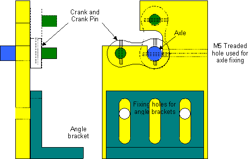
| The diagram on the above left shows two 3.3mm holes drilled for two M4 grub screws to clamp the crank onto the axle and the crank pin into the smaller hole on the crank. It is this �Clamping� mechanism that may have caused the running gear to work loose. Paul�s recommended modification to this securing of the crank onto the axle is shown in the diagram in the above middle, where the 3.3mm holes are drilled all the way through the axle and the crank pin. However, this solution introduces a more complex problem as when both ends of the axle are drilled, one end must be Quartered at the same time. There is also the added complexity of ensuring the cranks are positioned at right angles to the axles before they are drilled. In addition to this, unless you have an extra long M4 tap, you will not be able to tap all the way through the crank and the crank pin. My solution to this problem is shown in the above right diagram, where the 3.3mm drill holes don�t go al the way through the crank falling short by about 1.5mm to 2mm. |
| The crank pin is secured into the crank using a threaded pin, which may be cut from a suitable machine screw or threaded rod. Its length should be the width of the crank, less 1.5mm to 2mm. Across one end of the threaded pin cut a small slot, using a junior hacksaw, so that a screwdriver can be used to screw the threaded pin into the crank. At the other end of the threaded pin, reduce up to 4mm in length to be less than 3.3mm in diameter, using a lathe or hand file. Once finished, screw the threaded pin into tapped hole to secure the crank pin into the crank. When in tight, file off any of the threaded pin that is still protruding out of the crank. However, ensure that that there is still sufficient screwdriver slot depth to remove the pin later on, prior to final running gear assembly.
After securing the crank pin in the crank with the threaded pin, place the completed assembly in a lathe, holding the crank pin in the chuck jaws. If needed, face off, any of the crank pin that is protruding out of the crank, then drill a small centre hole, no more than 1mm deep, into the crank pin. This centre hole will be used later on to help quarter the cranks when place on to the axles. |
| The Quartering and Right Angle Jig |
| Installing the Cranks on to the Axles |
| Mounting the Coupling Rods |
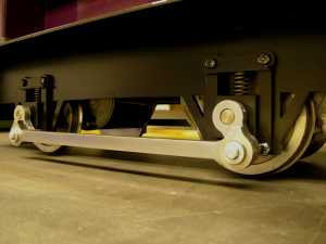
| The installation of the coupling rods is completed in exactly the same way as that described in the Trojan instruction manual. However, in my particular case I wanted to keep the metal finish on the coupling rods rather than paint them. Consequently, before silver soldering the bronze bearing on to the coupling rods I found it was easier to clean the rods up first, removing the remnants of the laser cutting. Although additional cleaning is required after the silver soldering process, the job is a little easier. The picture shown opposite is of the assembled running gear on the Trojan. |
| Warning
When inserting the M4 screw and washer into the crank pin to secure the coupling rods, it is necessary to add a small amount of Nutlock to secure the screw properly. However, make sure the Nutlock does not work its way along the screw thread and the washer becomes Nutlocked as well. As I found on the Trojan�s first outing after attaching the running gear, when a washer accidentally fixed by Nutlock became rather hot, even when the coupling rod had been lubricated beforehand. After releasing it, the washer was able to rotate freely and did not get hot any more. |
 |
| Installing the Crank Pins |
| First off place the crank pins in a lathe and face off the rough end of the pin (End without the centre hole) and reduce its length to the combined thickness of the crank and the length of the bronze bearing used for the coupling rod. In total I found the crank pin needed to be approximately 19mm long, but check this your self before starting. Once faced off, turn the crank pin round in the chuck (Centre hole outwards) and drill a 3.3mm hole approximately 11 mm deep and tap out to M4. |
 |
| Warning
Be careful when drilling. The laser cutting toughens the steel, which increases the chance if the drill bit snatching as it breaks through. Make sure the crank is firmly clamped whilst drilling. |
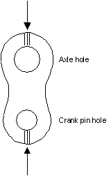
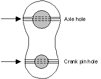
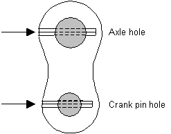
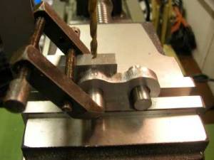
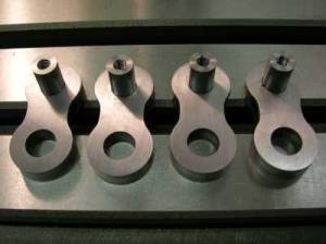
| The picture shown below left, is of the crank assembly mounted in a vice waiting to be drilled. The purpose of the engineers vice clamping an engineers square and the crank pin, is to ensure the crank pin is flush with the inside face of the crank. After drilling the 3.3mm hole to secure the crank pin, reposition the crank to drill the hole to secure the crank on to the axle. However, only drill, at most, a 5mm deep hole into the crank, which later on will provide a reference point for the hole that needs to be drilled into the crank and axle when using the Quartering jig described below. The picture shown below right is of the four finished cranks, with the M4 taped crank pins inserted and secured by M4 machine screws. |
 |
 |
| Suggestions
When tapping the M4 thread for the M4 machine screw or threaded rod, which secures the crank pin into the crank, start the tap with the crank pin inserted. As stated above, unless you have an extra long M4 tap, you will not be able to tap all the way through the crank and the crank pin. Consequently, when you have tapped as far as the tap will allow, finish off tapping the hole through the crank pin with it removed from the crank. |
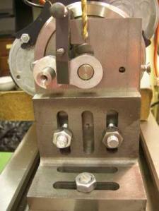
| The diagram shown below is of the quartering jig and the picture on the right is of the jig in use. After the crank, held in the horizontal position, has been drilled, taped and a modified machine screw or threaded rod inserted, fixing it on to the axle, the whole motor assembly is rotated clockwise 90 degrees and the crank on the other end of the axle is attached to it. The crank that was quartered first will now be in the vertical position as shown dotted in the diagram below. The small centre hole that was previously drilled into the opposite end of the crank pin from the M4 threads is used as a reference point to align the cranks in their horizontal and vertical positions. Seen in the above right hand picture are the two machine screws, seen on the inside faces of both jig plates, which are used to achieve this alignment. The threaded end of the machine screw has been filed to a point such that it locates into the small centre hole on the crank pin. |
 |
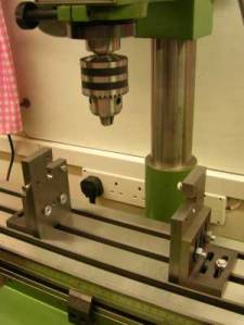 |
| Again the small engineers clamps were used to secure the previously assembled cranks in position on the axle while they were drilled and taped. The picture on the right is of the quartering jig set-up waiting for the axle assembly. Note the orientation of each end of the jig. |
 |
 |
 |