This is my current project, it is only a work in progress and the
box has not even been started yet.
It uses a Peerless CSX 10" subwoofer driver, this driver is very
versatile as it has a useable
response all the way up to 1KHz, and a very low fs for a 10"
woofer in its price range.
It does however call for a rather large box to obtain its low
frequency potential, this is the case
with other peerless drivers as well. My original plan was a Peerless
831857 12" driver, but it
would not give decent response until the box was 200L. So I changed my
Plan to the 850146.
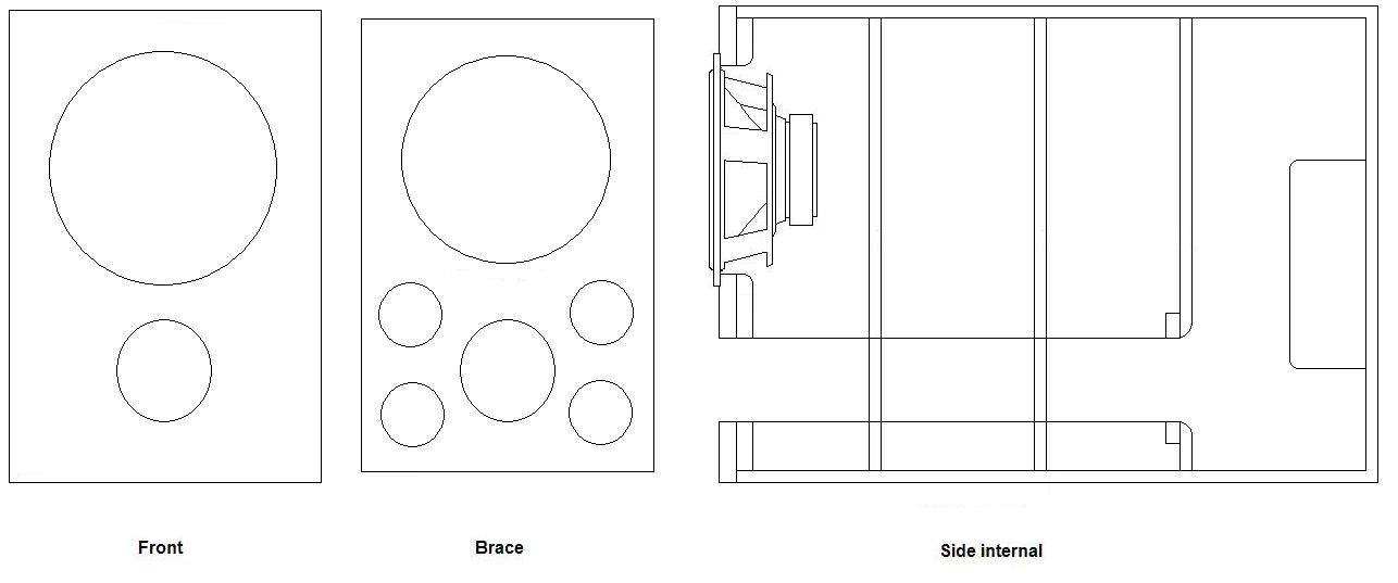
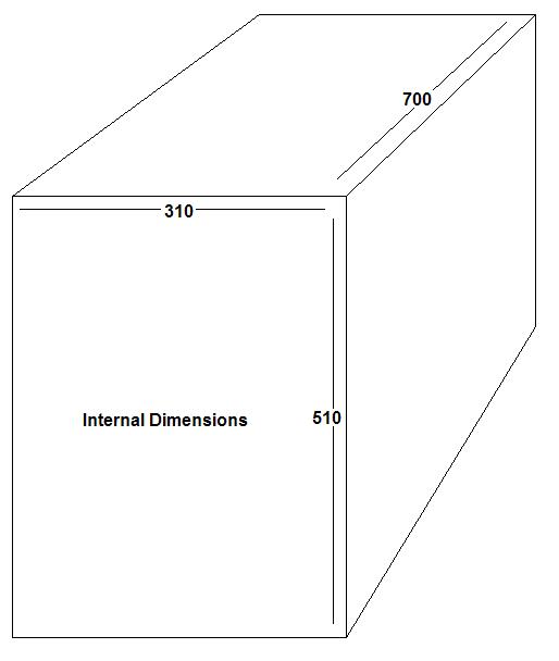
Here are some of my design plans for the cabinet.
Construction
Sketch
Dimensions
Sketch
Here are the drivers
specifications from the Peerless website.
Here are my predicted response curves done in WinISD.
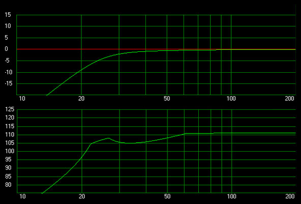
The top image is of the predicted response and the lower is of
the maximum SPL output.
Note that these are both predicted anechoic responses, in-room
response should be higher, especially in the low end.
As far as room gain goes it is too hard to determine the effects,
so as far as I go I will simply try to obtain the best theoretical
response
in hope that the room will not change it too much. I am also
considering room treatments to assist in eliminating nasty alterations
in the
response. When I move to a dedicated Home Theatre room I will
solve many of these problems.
I have now found a suitable filling to go in the box, it is this
open cell foam from Clark rubber, I will line all
internal walls with a single layer, it is only 15mm thick.
Update: I left the above paragraph as this is what I was going to
use but I had some foam off cuts that have taken that place free of
charge.
I will post pictures of the subwoofers construction as I go.
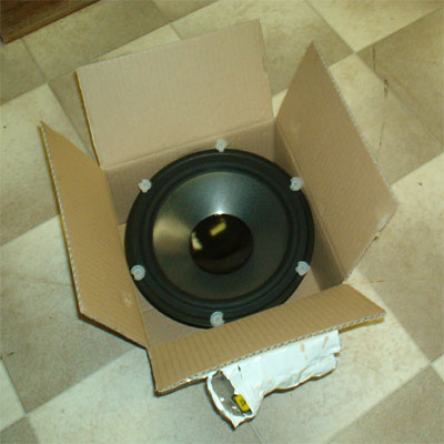
For now I will upload my construction plans and pictures of the
driver.
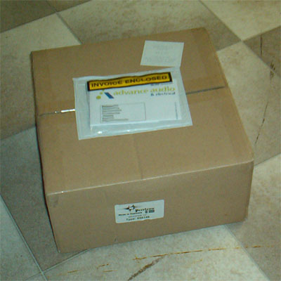
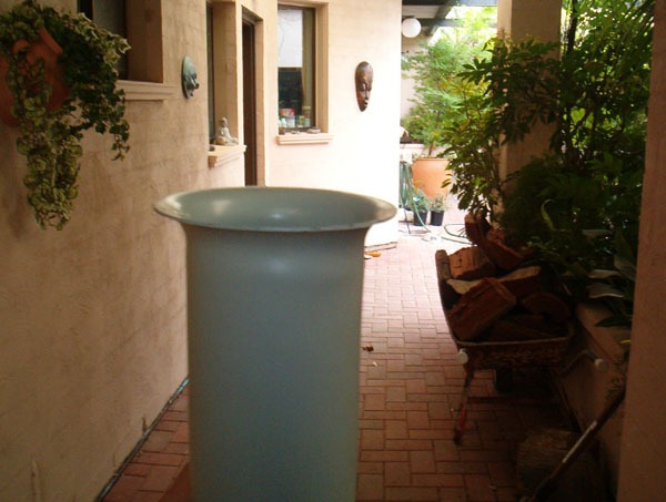
Here is the box as I got it, I don't know how I had the restraint to
get my camera and photograph it before opening it.
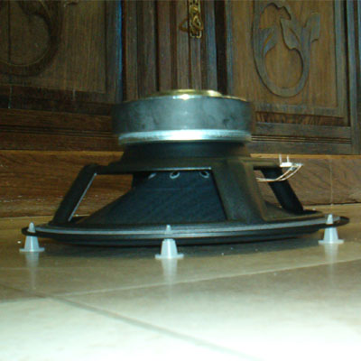
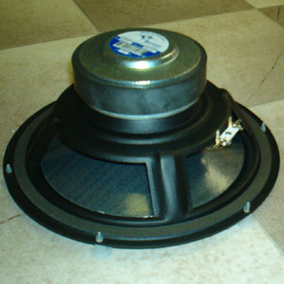
Here is the driver from behind, that basket is really stiff and
strong. The construction on this driver is really nice, alot more so
than
venom subwoofer. The small plastic things on the drivers edge were to
stop the surround touching the lid of the box, I thought I may
as well leave them on whilst I take pictures of the back.
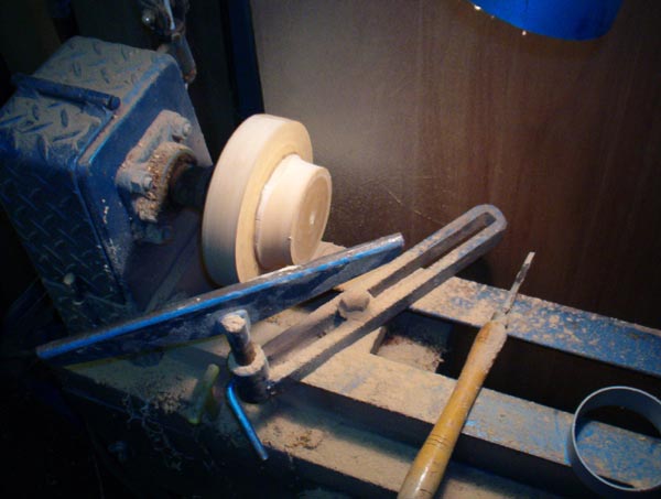
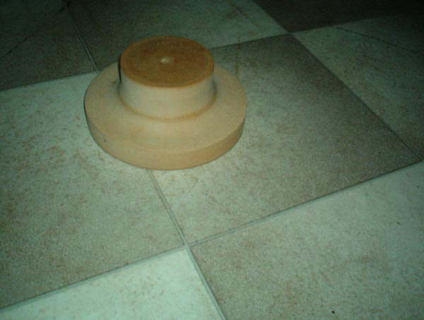
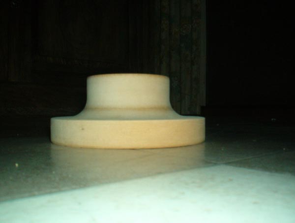
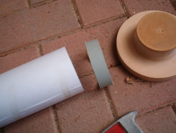
Here is the photos of the mould I am going to use to create my port
flares. It was made from 2 layers of 32mm MDF, turned on the
lathe to obtain the flare that I wanted.
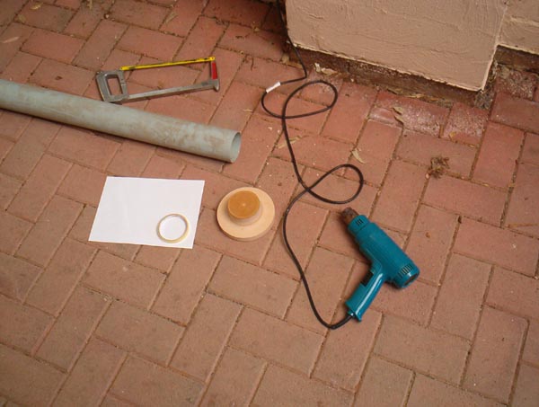
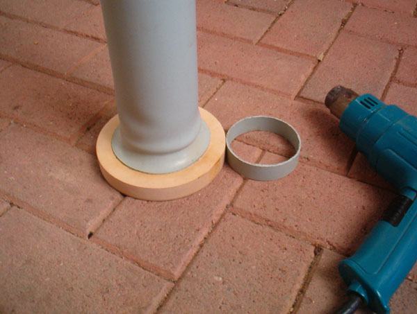
Here are tje tools used for the port flares followed by how to cut the
end of the pipe square.
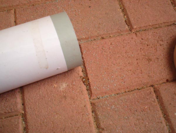
To cut the end of your pipe square wrap a piece of paper around the
end so that it lines up all the way around, then tape the
paper onto the pipe and cut with your hacksaw or similar blade.
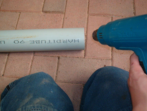
Apply heat to the end of the pipe, evenly all the way around
but only to the end 1-2cm, if you heat more than this you will end up
like my first attempt.
Here is my first attempt of three at flaring the port, due to too much
heat it did not flare much before
it began rippling and folding, the second was similar but not as bad.
Here is the final result, nice big flare and only a tiny hump that is
not visible
from the angle that it be placed in the box.
TIP when flaring, only
heat a small length at the end and heat it a moderate amount
then force it on the mould very hard, it will not tear, but if you try
and flare too much
the flare will fold back in on itself, but the amount I did it was
fine and is plenty enough.
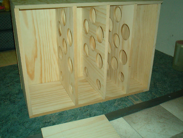
Here are some pics of when I first got all my timber and I put it
together to see if it all fitted well.
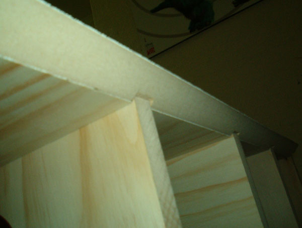
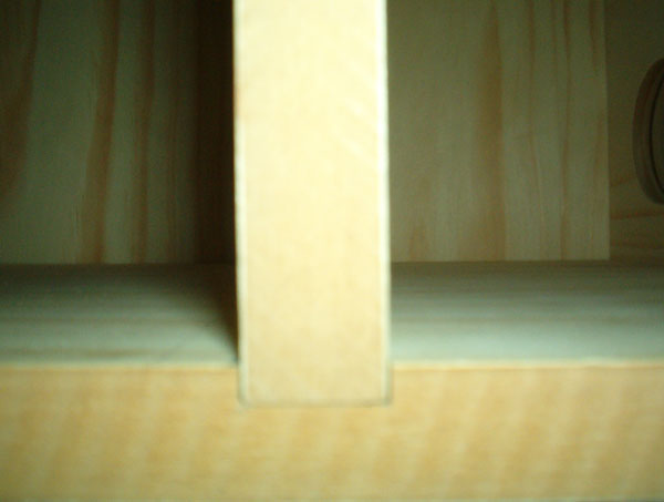
I featured some of the joints as these are some of the real strength
points of the structure.
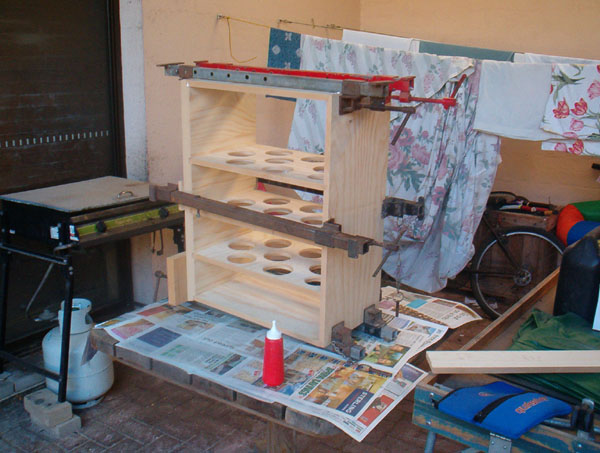
Here are 2 pictures of the initial gluing, had a great deal of
trouble squaring the box as when
stuck together one edge was bowed and so appeared square using the
corner to corner
measurement method but not with a square and vice versa, so additional
clamps had to be
used in the middle to obtain perfect squares. 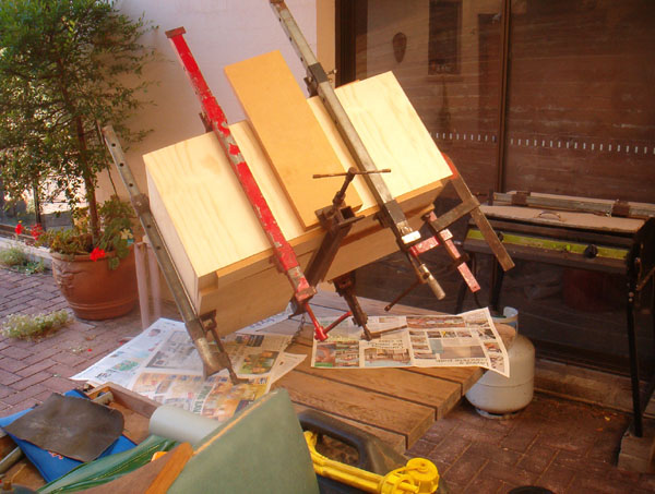
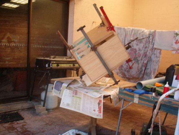
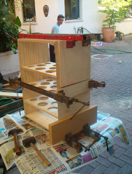
Here are some of the pictures of when I glued the first side on to the
box, this strange
balancing act was not done for its appearance, it was actually
done because my clamps
are very long and the shorter ones were too short, on top of that I
had to apply pressure
in a few different ways due to the 45" angled joins.
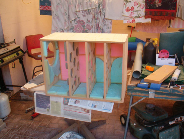
Here is the cabinet with the clamps taken off and the internal foam
glued in place.
This so far has exhausted all my PVA glue.
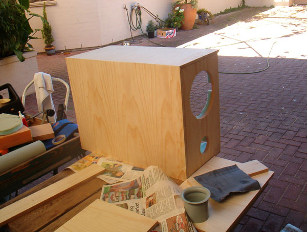
The sub is now at the stage where it is in my room and is fully
operational. I have yet to paint/stain
the cabinet but it is working and the results are below.
Listening Impressions:
in the beginning I found the sub to be very very clean and smooth,
though lacking the midbass punch
of so many commercial subwoofers and car subwoofers. I had discovered
that the bass that I had
made was not the kind that my home theatre was after. Hence my next
project.
In retrospect and after many weeks of listening i can say that the sub
performs VERY well for any
moderate music duties and HT duties alike, though it quickly runs out
of grunt for any kind of loud
listening, it cannot reach the stage of chest ratting or even
thumping.
But a very nice sounding sub all the same, perhaps better suited as
the lower end in some full range
speakers, but for a sub it is not the best considering the size of the
cabinet.
|