| Description | ||
|
SECTION 1 Introduction Deliverable Description
SECTION 2
SECTION 3
SECTION 4
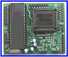
(Above) 8051 (GB) micro controller
* The controller's code was written in C++.... it was too large for Assemble Language.
|
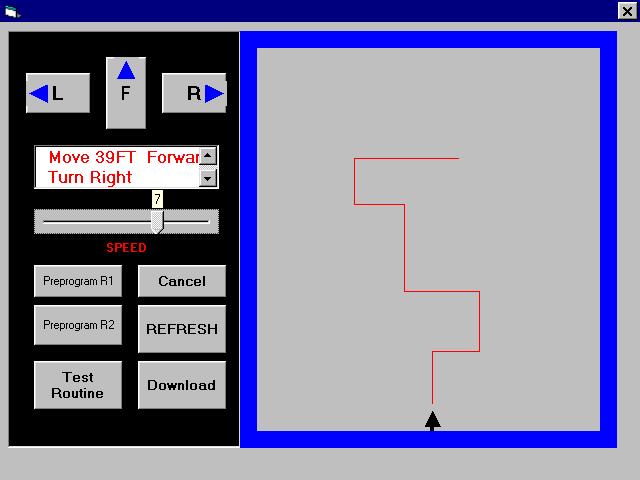
The objective of this project
is to design and build a semi-autonomous robot and an interface system
to interact with it. The concept of operation is to enter navigational
type information from a desktop computer using a visual basic interface.
The information is then downloaded to the robot through a serial
port connection. The robot will initialize both rear wheels; it will
then interpret the downloaded information and move from its “home”
position to the new location directed by the user and then return to its
home position. Additionally,
the robot is able to avoid object(s) within its path. The interface serves five
basic functions. These are: (1) To give the user a graphical
representation of the proposed path, (2) To translate and display the
proposed path into English like statements (3) To be user friendly, thus
taking into account that the user may make mistakes while entering
information, it uses message boxes as an aid to the user
(4) To create a file, which contain pertinent information about
the proposed path, which will be downloaded, (5) allow the user to
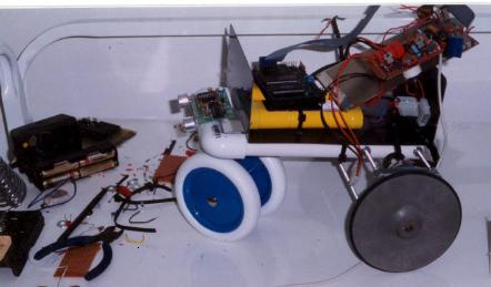
set/vary the speed of the robot. The robot’s design mimics
that of a tricycle. It is
driven by both rear wheels, which are kept in synchronization by a
closed-loop control system. Turning is accomplish by reversing one of
the rear wheels while the other rotates forward for a predetermine
numbers of pulses. The electronics include: Controller (Intel GB200),
Sensors (Ultra sonic), Digital to Analog converser (DAC), Pulse Width
Modulation (PWM) drives and opto-isolators. The file that is downloaded
to the controller from the VB interface consists of a series of tag/data
combination; these numbers are converted to hex values before they are
stored. This sequential tag/data arrangement is terminated by the number
“63”. At the mid-point of this file there is the tag/data of
“62/16”; this actually calls the subroutine “turn around” where
the robot rotates 180°.
In the second half of this file all the tags are reverse (i.e. left
becomes right and visa versa) and the tag/data arrangement are
re-positioned to reflect a return to home sequence. The tags are:
01-which means “ move forward” where the parameters are setup
to move forward and the data that follows tells the distance; 02- which
means “turn left” where the parameters are set to turn left and the
data that follows is an indication of the angle; 03- which means “turn
right” where the parameters are set to turn right and the data that
follows is an indication of the angle. Each tag calls a different
subroutine, the functions of these subroutines are to set the desired
parameters for /and perform the function of: turning right, left or go
forward. Additionally, the controller
has three other sub-routines to be able to call. These routines are:
(1) Table1 routine – this routine creates an array, which is 50
bytes long and is used to hold the downloaded tag-data combinations for
moving from home to destination to home (terminated by the # 63 or 3F
hex). This only occurs
whenever the download switch on the control panel is pressed and
released. (2) Run – this routine is
called whenever the run switch is pressed. The controller cycles through
the downloaded file, reading and interpreting all the tag/data
arrangements. In this process the robot is moved from home to
destination to home. The controller exits this routine when a tag of 63
(3F hex) is detected. (3) Align routine – this
routine aligns the wheels whenever the align-switch is pressed and
released on the control panel. After the alignment both clocks are
sitting at a high level. Additionally,
there is another push-button switch on the control panel – “run
switch”. When this switch
is pressed and released, the controller runs the downloaded instructions
by sequencing through both arrays-1 & 2.
This causes the robot to move from home to destination and back. Mounted on both rear wheels are opto-interrupter modules,
which straddle a toothed wheel. These modules send out clock pulses, as
the teeth on the wheel interrupts the light path of the opto-interrupter
modules. These pulses are
read by the controller. The controller uses these pulses to determine
the position of the robot and if the wheels are moving in sync. The synchronization of the
wheels is done by constantly monitoring both wheels together. To
accomplish this, the controller reads each clock from both wheels at the
same time. It then sits in a loop waiting for a transition from high to
low (or low to high) to occur on either or both of the clocks. If only
one transition occurs, the assumption is made that the corresponding
motor is leading the other. The controller instantly pulses the leading
motor off and allows the lagging motor to catch up. When both motors are
again synchronized, the controller turns the leading motor back on and
cycles trough this loop again. The number of cycles trough this loop is
directly proportional to the distance entered.
To determine the distance
traveled, the controller equates each pulse to a certain distance.
This resolution was measured and found to be .7 inch per pulse.
The distance traveled is translated into counts by (count =
distance / 0.7in. per count) where distance is measured in inches. As
the robot travels, the number of pulses measured is constantly being
compared with the initial count value until the desired count (distance)
is reached.
|