Electronic schematics and high voltage transformer.
The electronics basically consist of an oscillator and a high voltage transformer. The high voltage transformer used is commonly found in old black&white televisions and is called a LOPT or “flyback” transformer. This transformer consists of a small ferrite core and a disk-shaped secondary. It cannot be operated at conventional frequencies like 50 or 60 Hz but utilizes frequencies above 10 Khz at a voltage of 8 to 12 thousand volt. Luckily this makes it ideal for operating plasma-globes as they require high voltage high frequency AC to operate.
As you can see in the pictures to the right, the original primary windings are removed. This is because the oscillator only needs a 8 to 10 turns center-tapped primary of thick wire. I used speaker-wire. It's not the best choice but it is easy to come by and easy to wind.
Oscillator
The circuit to “drive” the transformer is a very simple oscillator. I kindly borrowed the design of the oscillator from the HV Community forum at 4hv.org. Search for “zvs flyback driver” at this forum to learn more about its properties. Note that this driver is far superior to the commonly known 555 timer or single transistor driven flyback circuits out there. It also uses very little components and is therefore cheap and easy to make.
Instead of using a 0.68 uF capacitor i used a 100 nF capacitor. And instead of 5+5 turns on the core i used 4+4 turns. This makes the operating frequency pretty high as it is the resonant frequency of the LC circuit formed by the capacitor and the total inductance of all 8 turns on the primary of the flyback. I am currently feeding the circuit about 35 volts rectified AC via a variac which is about 50 volt DC. For the globe to work one of the flyback secondary wires needs to be grounded. You can do this be putting a clamp on your central heating pipes like i did. Or drive a copper tube into the ground and attach a wire to it.
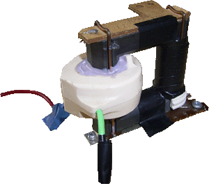
This transformer has it's primary windings removed. You can clearly see the thick plastic housing of the high voltage secondary. The red wire is used as the ground.
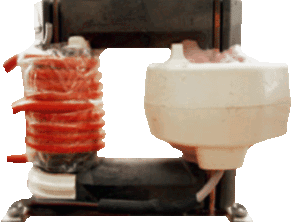
The same transformer with new primary windings. Due to the high frequency, eight to ten turns of primary windings is all it takes. Don't be tempted to wind many more as this will quickly degrade performance.
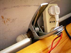
The groundclamp on the central heating pipes. Attached via a wire to one of the outputs of the flyback transformer. Without it, nothing works.