 |
|
|
|
|
|
|
|
|
|
|
|
|
|
|
|
|
|
|
|
|
|
|
|
|
|
|
|
|
|
|
|
|
|
|
|
|
|
|
|
|
|
|
|
|
|
|
|
|
|
|
|
|
|
|
Bouwfoto's deel 6. |
|
|
|

|
|
|
|
|
|
 |
|
 |
|
|
|
|
|
 |
|
|
|
|
 |
|
|
|
|
|
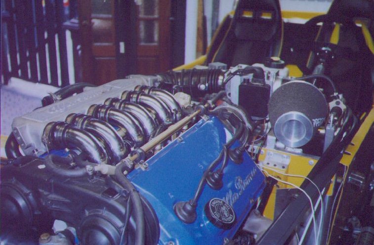
Tussen deel 5 en deel 6 vond het grote moment plaats dat er voor het eerst de de auto kon worden gereden. Helaas helaas was er iets mis in de motor waardoor deze op ongveer 4.5 cilinders liep. Een scheefliggend klepstelplaatje en een verbogen bougie elektrode waren hiervan de oorzaak. Toen liep de motor zoals een Alfa 6 cilinder hoort te doen. Maar helaas stond de auto toen al weer op z'n bokjes.
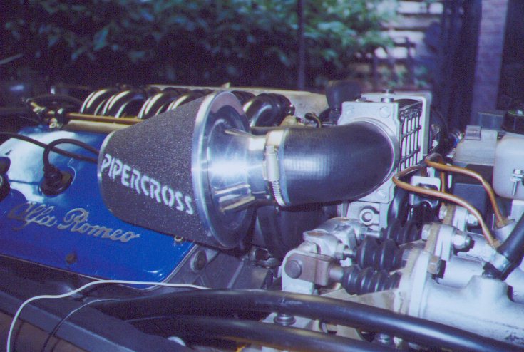
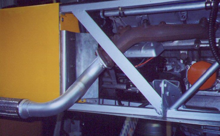
Op deze foto's het uiteindelijk inlaatspruitstuk. In eerder bouwfoto's hebben jullie kunnen zien dat er een ander inlaatspruitstuk op heeft gezeten. Daarna had ik de plannen zelf een inlaat te maken. Uiteindelijk heb ik de makkelijk manier gekozen en zie hier het resultaat. Het standaard spruitstuk van de 164 V6, echter met de inlaatbuis van de Alfa 75 V6. Tenslotte de luchtmeter rechtop in plaats van liggend en een Pipecross luchtfilter. Zoals het nu ingebouwd is is 't alsof het ervoor gemaakt heeft moeten zijn. |
|
|
|
|
|
|
A very important moment took place between part 5 and 6. A first testdrive was made. Unfortunately the engine was running on 4.5 cilinders. A wrong places valve adjust plate (I couldn't find the right English word for this) and a broken spark plug were the teasons of this fact. After these two small modifications the engine was running like an Alfa V6 has to do.
On these picturess you can see the final intake manifold. In urlier part you could see another intake manifold from the Alfa 75 V6 and later I was planning to build one myself. But I've chosen for the easy way and used the intake manifold from the 164 V6. |
|
|
|
|
 |
|
|
|
|
|
|
De voorpijpen, gelast door Willem (V8 chevy Rush). Vakwerk. |
|
|
|
|
|
The first pipe from the exhaust system. Welded by Willem, a masterjob. |
|
|
|
|
|
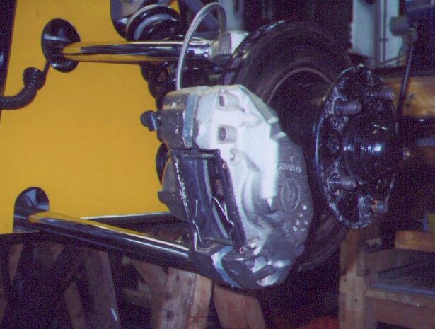
De voorremmen van de Ford Granada 2.8 V6. 5-gaats, geventileerd. Klauwen zijn gereviseerd. De schijf moet echter iets afgedraaid worden (2 tot 3 mm) omdat ie anders te groot is. Tegenwoordig is het ook mogelijk Sierra fusee's en remmen te gebruiken. Zelfs Cosworth remmen (4 zuiger remklauwen) zijn dan mogelijk. De draagarmen zijn dan ook langer omdat de vorm van de fusee smaller is. De spoorbreedte neemt dan ook toeModificateis voor over een paar jaar. |
|
|
|
 |
|
|
|
|
Brake disic and calipers from the Ford Granada 2.8 V6. The discs have to be turned off for about 2 to 3 mm. Otherwise they will not fit through the calipers. From this modelyear (2000) Sierra uprights and brakes are also possible. Even Cosworth 4 cilinders brakecalipers should be possible. You also have to have other wishbones because of other dimensions from the uprights. The front track will increase also. |
|
|
|
|
|
|
 |
|
|
|
 |
|
|
|
|
|
 |
|
 |
|
|
|
|
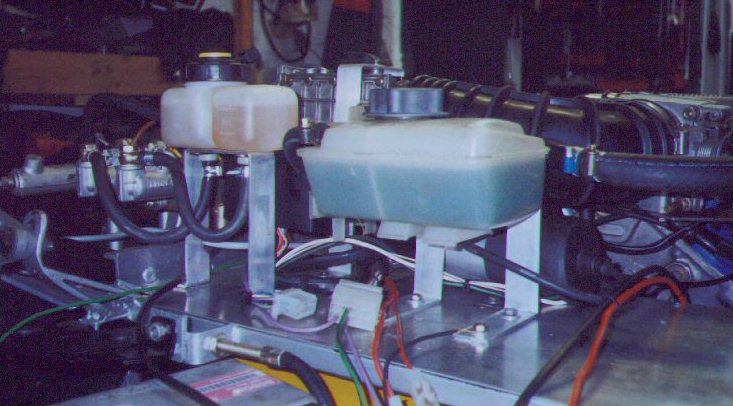
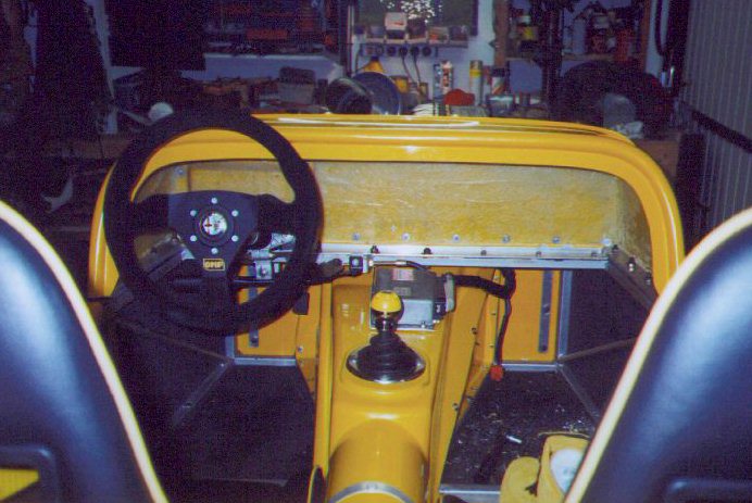
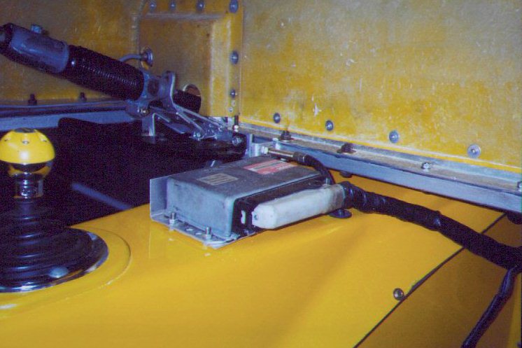
Het dasboard op z'n plek althans the houder. In het engels hebben ze daar tenminste een woord voor (centre scuttle). Hier waren wat aanpassingen voor nodig omdat er nogal een grote kier open bleef. Een aluminium hoekprofiel (40x40) bracht de oplossing.
Injectiecomputer op z'n plek (Motronic ML 4.1) en de schakelaars van de voetrem en de handrem. Voor de voetrem zit er eigenlijk een drukschakelaar in de leiding opgenomen. Deze schakeld echter iets later dan wanneer er een schakelaar bij het pedaal wordt gebruikt. En omdat deze auto stukker harder remt dan een achterligger......... |
|
|
|
|
|
The centre scuttle in place. A view modification had to be made to fill up a big jar. A 40x40 aluminium profile was the solution. Also the engien management coputer in place (Bosch Motronic ML 4.1). On the last picture you could see two switches. One for foot braking and one for hand braking. I will not use the pressure switch in the brake line because of the delay. This car will brake much faster then the one behind you........... |
|
|
|
|
|
|
 |
|
|
|
 |
|
|
|
|
|
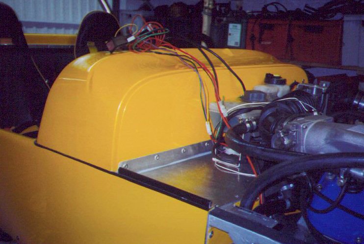
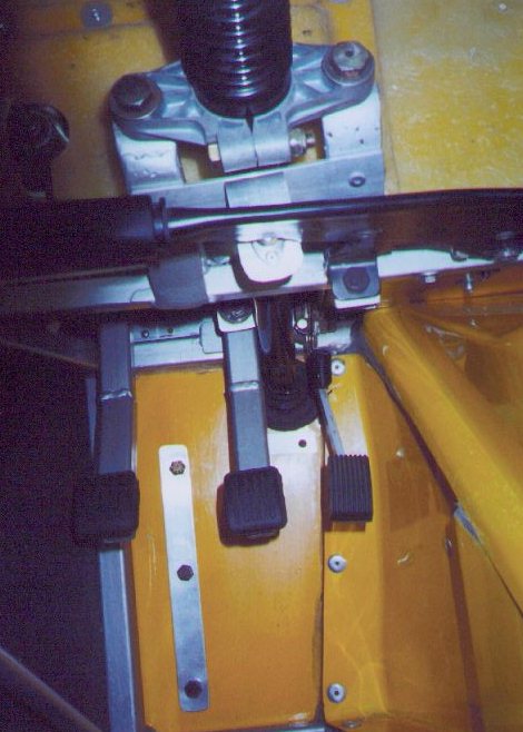
De enige oplossing om de pedalenbox af te dekken. Het was een enorme klus wat pas en meetwerk betreft maar het reslutaat mag er zijn. Om ook de beweging van de pedalen op te vangen is een stukje rubber (binnenband) geplaatst. |
|
|
|
The only solution to isolate the engine bay from the inner room ate the pedalbox. It was a terrible job but I'm very saticfied with the result. An piece of inner tube is used to fill the holes for the movement from the pedals. |
|
|
|
 |
|
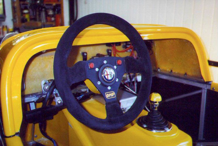
Omdat ik geen stuurkolomschelaar meer heb moest er iets anders verzonnen worden voor de richtingaanwijzers. Zie hier de Formule 1 oplossing. Schakelaartjes op het stuur. In de schakelaar zit een LED die meeknippert. TOP ! |
|
|
|
|
|
Because of the fact that I didn't have any steeringrack switches anymore some solution had to be find for the indicator switches. This Formula 1 solution was made. Two switches which contains a LED that will flash together with the indicators. |
|
|
|
|
|
Terug naar deel 5
Back to part 5 |
|
Verder naar deel 7
To part 7 |
|
|
|
 |
|
|
|
|
|
|
|
 |
|