Resistors
A resistor is a two-terminal electrical or electronic component that resists an electric current by producing a voltage drop between its terminals in accordance with Ohm's law: r=v/i
Identifying resistors
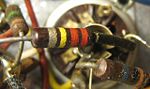 Most axial resistors use a
pattern of colored stripes to indicate
resistance. Surface-mount ones are marked numerically. Cases are usually
brown, blue, or green, though other colors are occasionally found such as
dark red or dark gray.
Most axial resistors use a
pattern of colored stripes to indicate
resistance. Surface-mount ones are marked numerically. Cases are usually
brown, blue, or green, though other colors are occasionally found such as
dark red or dark gray.
One can also use a multimeter or ohmmeter to test the values of a resistor.
Four-band axial resistors
Four-band identification is the most commonly used color coding scheme on
all resistors. It consists of four colored bands that are painted around the
body of the resistor. The scheme is simple: The first two numbers are the
first two significant digits of the resistance value, the third is a
multiplier, and the fourth is the tolerance of the value. Each color
corresponds to a certain number, shown in the chart below. The tolerance for
a 4-band resistor will be 2%, 5%, or 10%.
Preferred values
Resistors are manufactured in values from a few milliohms to about a gigaohm;
only a limited range of values from the IEC 60063 preferred number series
are commonly available. These series are called E6, E12, E24, E96 and E192.
The number tells how many standardized values exist in each decade (e.g.
between 10 and 100, or between 100 and 1000). So resistors conforming to the
E12 series, can have 12 distinct values between 10 and 100, whereas those
confirming to the E24 series would have 24 distinct values. In practice, the
discrete component sold as a "resistor" is not a perfect resistance, as
defined above. Resistors are often marked with their tolerance (maximum
expected variation from the marked resistance).
5-band axial resistors
5-band identification is used for higher precision (lower tolerance)
resistors (1%, 0.5%, 0.25%, 0.1%), to notate the extra digit. The first
three bands represent the significant digits, the fourth is the multiplier,
and the fifth is the tolerance. 5-band standard tolerance resistors are
sometimes encountered, generally on older or specialized resistors. They can
be identified by noting a standard tolerance color in the 4th band. The 5th
band in this case is the temperature coefficient.
Technology
Carbon composition
Carbon composition resistors consist of a solid cylindrical
resistive element with embedded wire leadouts or metal end caps
to which the leadout wires are attached, which is protected with
paint or plastic. A spiral is used to increase the length and
decrease the width of the film, which increases the resistance.
The resistive element is made from a mixture of finely ground
(powdered) carbon and an insulating material (usually ceramic).
The mixture is held together by a resin. The resistance is
determined by the ratio of the fill material (the powdered
ceramic) and the carbon. Higher concentrations of carbon, a weak
conductor, result in lower resistance. Carbon composition
resistors were commonly used in the 1960s and earlier, but are
not so popular for general use now as other types have better
specifications, such as tolerance, voltage dependence, and
stress (carbon composition resistors will change value when
stressed with over-voltages).
Thick and thin film
Thick film resistors became popular during the 1970s, and most
SMD resistors today are of this type. The principal difference
between "thin film" and "thick film resistors" isn't necessarily
the "thickness" of the film, but rather, how the film is applied
to the cylinder (axial resistors) or the surface (SMD
resistors). In thick film resistors the "film" is applied using
traditional screen-printing technology.
Thin film resistors are made by sputtering the resistive
material onto the surface of the resistor. Sputtering is
sometimes called vacuum deposition. The thin film is then etched
in a similar manner to the old (subtractive) process for making
printed circuit boards: ie the surface is coated with a
photo-sensitive material, then covered by a film, irradiated
with ultraviolet light, and then the exposed photo-sensitive
coating, and underlying thin film, are etched away.
Thin film resistors, like their thick film counterparts, are
then usually trimmed to an accurate value by abrasive or laser
trimming.
Because the time during which the sputtering is performed can be
controlled, the thickness of the film of a thin-film resistor
can be accurately controlled. The type of the material is also
usually different consisting of one or more ceramic (cermet)
conductors such as tantalum nitride (TaN), ruthenium dioxide
(RuO2), lead oxide (PbO), bismuth ruthenate (Bi2Ru2O7), nickel
chromium (NiCr), and/or bismuth iridate (Bi2Ir2O7).
By contrast, thick film resistors, may use the same conductive
ceramics, but they are mixed with sintered (powdered) glass, and
some kind of liquid so that the composite can be screen-printed.
This composite of glass and conductive ceramic (cermet) material
is then fused (baked) in an oven at about 850 °C.
Traditionally thick film resistors had tolerances of 5%, but in
the last few decades, standard tolerances have improved to 2%
and 1%. But beware, temperature coefficients of thick film
resistors are tyically ±200 ppm, or ±250 ppm, depending on the
resistance. Thus a 40 degree Celsius (70 °F) temperature change
can add another 1% variation to a 1% resistor.
Thin film resistors are usually specified with tolerances of
0.1, 0.2, 0.5, and 1%, and with temperature coefficients of 5 to
25 ppm. They are usually far more expensive than their thick
film cousins. Note, though, that SMD thin film resistors, with
0.5% tolerances, and with 25 ppm temperature coefficients, when
bought in full size reel quantities, are about twice the cost of
a 1%, 250 ppm thick film resistors.
Metal film
A common type of axial resistor today is referred to as a
metal-film resistor. MELF (Metal Electrode Leadless Face)
resistors often use the same technology, but are a cylindrically
shaped resistor designed for surface mounting. [Note that other
types of resistors, eg carbon composition, are also available in
"MELF" packages].
Metal film resistors are usually coated with nickel chromium (NiCr),
but might be coated with any of the cermet materials listed
above for thin film resistors. Unlike thin film resistors, the
material may be applied using different techniques than
sputtering (though that is one such technique). Also, unlike
thin-film resistors, the resistance value is determined by
cutting a helix through the coating rather than by etching.
[This is similar to the way carbon resistors are made.] The
result is a reasonable tolerance (0.5, 1, or 2%) and a
temperature coefficient of (usually) 25 or 50 ppm.
Wirewound
Wirewound resistors are commonly made by winding a metal wire
around a ceramic, plastic, or fiberglass core. The ends of the
wire are soldered or welded to two caps, attached to the ends of
the core. The assembly is protected with a layer of paint,
molded plastic, or an enamel coating baked at high temperature.
The wire leads are usually between 0.6 and 0.8 mm in diameter
and tinned for ease of soldering. For higher power wirewound
resistors, either a ceramic outer case or an aluminium outer
case on top of an insulating layer is used. The aluminium cased
types are designed to be attached to a heatsink to dissipate the
heat; the rated power is dependant on being used with a suitable
heatsink, e.g., a 50 W power rated resistor will overheat at
around one fifth of the power dissipation if not used with a
heatsink.
Because wirewound resistors are coils they have more inductance
than other types of resistor, although this property can be
minimized by winding the wire in sections with alternately
reversed direction.
Foil resistor
Foil resistors have had the best precision and stability ever
since they were introduced in 1958 by Felix Zandman. One of the
important parameters influencing stability is the temperature
coefficient of resistance (TCR). Although the TCR of foil
resistors is considered extremely low, this characteristic has
been further refined over the years.[1]
Failure modes and pitfalls
Like every part, resistors can
fail; the usual way depends on their construction. Carbon
composition resistors and metal film resistors typically fail as
open circuits. Carbon-film resistors typically fail as short
circuits.
Various effects become important in high-precision applications.
Small voltage differentials may appear on the resistors due to
thermoelectric effect if their ends are not kept at the same
temperature. The voltages appear in the junctions of the
resistor leads with the circuit board and with the resistor
body. Common metal film resistors show such effect at magnitude
of about 20 µV/°C. Some carbon composition resistors can go as
high as 400 µV/°C, and specially constructed resistors can go as
low as 0.05 µV/°C. In applications where thermoelectric effects
may become important, care has to be taken to e.g. mount the
resistors horizontally to avoid temperature gradients and to
mind the air flow over the board