Colada Continua / Continuous Casting

AHMSATECH • Cokemaking • Sinter • Pellet • Ironmaking • Continuos Casting • BOF • Rolling


Regresar / Back

Descripción de Proceso

Process Description

Instalaciones

Facilities

Artículos

Papers


El proceso de Colada Continua


Tradicionalmente el acero líquido obtenido de los hornos de aceración, ya sea de BOF o Siemens-Martin, era colado en moldes para su solidificación, de ahí se obtienen lingotes los cuales es necesario recalentar para poder laminarlos en el molino desbastador y obtener productos intermedios de dimensiones adecuadas que puedan ser utilizados en los molinos acabadores para obtener un producto final. 
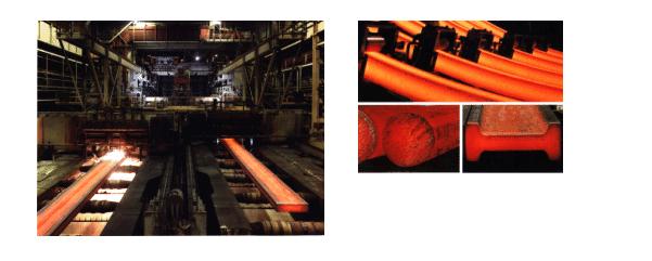
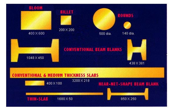
Estos productos intermedios son: planchón, tocho y bilete.


Con el propósito de incrementar el rendimiento de acero líquido a producto terminado, y el de evitar los pasos de recalentamiento y desbaste, se efectuaron pruebas para obtener los productos intermedios directamente de la colada. El resultado de estas pruebas fue el nacimiento de la colada continua.
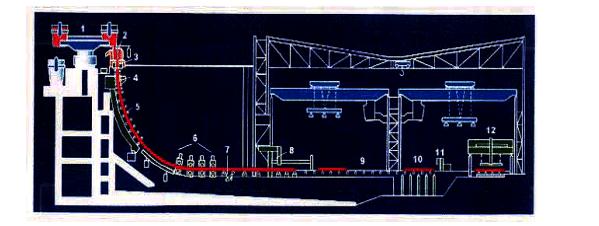
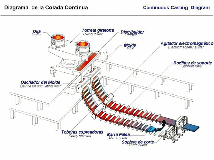
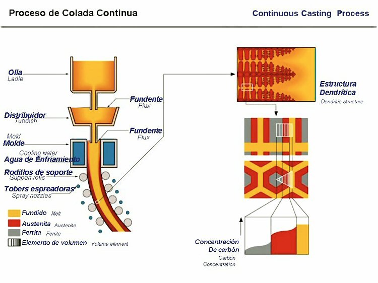


Partes principales de una colada continua.


DISTRIBUIDOR. Artesa o caja revestida con material refractario que cuenta con un orificio de salida de acero en cada uno de los extremos, y al fondo de los cuales por medio de mecanismos manuales de barra, tapón y tobera de descarga sumergida, se alimentan los moldes de colada continua y donde se almacena el acero para permitir el cambio de ollas durante la operación de una secuencia.


MOLDE. Pieza fabricada de placas de cobre (material de alta conductividad térmica) que cuenta con refrigeración interna y recibe el acero líquido del distribuidor.


RODILLOS GUIA. Toda una serie de éstos van colocados por debajo de los moldes para ir formando un hilo.


SECCION DE CORTE. Equipo necesario para dimensionar el planchón por corte normalmente del tipo oxiacetileno.


El proceso.


Antes de iniciar una colada, es necesario preparar la máquina. Esta preparación consiste en sellar el molde de cobre por la parte inferior. Para realizar esta operación se introduce por la parte más baja de los rodillos guía una pieza de acero semejante en dimensiones al planchón que se va a obtener, esta pieza es llamada barra falsa. Al tener la barra en la parte inferior del molde, se le colocan piezas pequeñas de acero (rebabas, viruta, etc.) que sirven como agentes de enfriamiento y permiten que el acero que es vaciado al molde, solidifique y se adhiera a la barra falsa, con lo cual será posible ir jalando al planchón del molde a través de los rodillos guía.
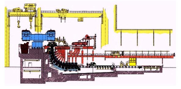
 

Una vez preparada la máquina, la olla de acero provinente del taller de aceración BOF se coloca en la torreta; la cual a su vez se coloca arriba del distribuidor, éste recibe el acero de la olla y lo reparte en los moldes que conforman la máquina.


El molde es enfriado continuamente por las caras externas. La solidificación del acero principia con el que está en contacto con el molde, y conforme pasa el tiempo, la capa sólida va aumentando hacia el centro. El molde se llena hasta el nivel de operación y se inicia o entra a trabajar al sistema de oscilación vertical del mismo molde; estas oscilaciones permiten y facilitan el deslizamiento del planchón hacia abajo del molde y es conducido por los rodillos que van curvándolo para dejarlo en posición horizontal al terminar el hilo. Durante el paso del planchón por los rodillos guía, éste es enfriado por un esperado de agua hasta su completa solidificación.
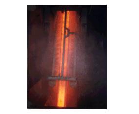
 

A la salida de los rodillos guía se encuentran las máquinas de oxicorte para obtener planchón de las longitudes requeridas para procesos posteriores. El planchón ya cortado se almacena en el patio para después enviarse a la sección o departamento de laminación correspondiente.


Regresar / Back


Continuous Casting Process


Continuous Casting of Steel: Basic Principles


Background | Production and Feasibility Study | Casting Overview | Liquid Steel Transfer
Tundish Overview | Mold | Mold Oscillation | Secondary Cooling
Shell Growth | Strand Containment | Bending and Straigtening | Summary

Background

Continuous Casting is the process whereby molten steel is solidified into a "semifinished" billet, bloom, or slab for subsequent rolling in the finishing mills. Prior to the introduction of Continuous Casting in the 1950s, steel was poured into stationary molds to form "ingots". Since then, "continuous casting" has evolved to achieve improved yield, quality, productivity and cost efficiency. Figure 1 shows some examples of continuous caster configurations.

Figure 1 - Examples of Continuous Casters

Steel from the electric or basic oxygen furnace is tapped into a ladle and taken to the continuous casting machine. The ladle is raised onto a turret that rotates the ladle into the casting position above the tundish. Referring to Figure 2, liquid steel flows out of the ladle (1) into the tundish (2), and then into a water-cooled copper mold (3). Solidification begins in the mold, and continues through the First Zone (4) and Strand Guide (5). In this configuration, the strand is straightened (6), torch-cut (8), then discharged (12) for intermediate storage or hot charged for finished rolling.

Figure 2 - General Bloom/Beam Blank Machine Configuration

1:Ladle Turret, 2:Tundish/Tundish Car, 3:Mold, 4:First Zone (Secondary Cooling), 5:Strand Guide (plus Secondary Cooling), 6:Straightener Withdrawal Units, 7:Dummy Bar Disconnect Roll, 8:Torch Cut-Off Unit, 9:Dummy Bar Storage Area, 10:Cross Transfer Table, 11:Product Identification System, 12:Product Discharge System

Figure 3 depicts a Slab Caster layout. Note the extended roller containment compared to that for a Bloom/Beam Blank (as in Figure 2), required to maintain product shape through final solidification.

Depending on the product end-use, various shapes are cast (Figure 4). In recent years, the melting/casting/rolling processes have been linked while casting a shape that substantially conforms to the finished product. The Near-Net-Shape cast section has most commonly been applied to Beams and Flat Rolled products, and results in a highly efficient operation. The complete process chain from liquid metal to finished rolling can be achieved within two hours.

Figure 3 -Slab Caster Layout


Figure 4 - Continuous Cast Shapes (sizes in millimeters)

To Top

Production and Feasibility Study

This is the first step in designing a continuous caster. First, the product end-use dictates the quality, grade and shape of the cast product (billet, bloom, slab, beam blank, and/or round). Considerations are then made based on desired annual tonnage, liquid steel availability, and anticipated operating hours. Then, the machine design considerations can be made for the number of strands and cast speeds to match the liquid metal supply from the melt shop.

Quality and grade considerations are then utilized in determining various design parameters of the casting machine such as its length, vertical height, curved or straight mold, water versus water/air secondary cooling, electromagnetic-stirring, etc.

To Top

Casting Overview

To start a cast, the mold bottom is sealed by a steel dummy bar, which is held in place hydraulically by the Straightener Withdrawal Units (Figure 2, item 6). This bar prevents liquid steel from flowing out of the mold. The steel poured into the mold is partially solidified, producing a steel strand with a solid outer shell and a liquid core. In this primary cooling area, once the steel shell has a sufficient thickness, about 0.4 - 0.8 inches (10 to 20 mm), the Straightener Withdrawal Units are started, and proceed to withdraw the partially solidified strand out of the mold along with the dummy bar. Liquid steel continues to pour into the mold to replenish the withdrawn steel at an equal rate. The withdrawal rate depends on the cross-section, grade and quality of steel being produced, and may vary between 12 and 300 inches per minute. Casting time is typically 1.0 - 1.5 hours per heat to avoid excessive ladle heat losses.

Upon exiting the mold, the strand enters a roller containment section and secondary cooling chamber (Figure 2, items 4 & 5) in which the solidifying strand is sprayed with water, or a combination of water and air (referred to as Air-Mist) to promote solidification. This area preserves cast shape integrity and product quality. Larger cross-sections require extended roller containment (Figure 3). Once the strand is fully solidified and has passed through the Straightener Withdrawal Units, the dummy bar is disconnected, removed and stored. Following the straightener, the strand is cut into individual pieces of the following as-cast products: slabs, blooms, billets, rounds, or beam blanks, depending on machine design.

Billets have cast section sizes up to about 7 inches square. Bloom sections sizes typically range from approximately 7 inches square to about 15 inches by 23 inches. Round castings include diameters of approximately 5 to 20 inches. Slab Castings range in thickness from 2 to 16 inches, and over 100 inches wide. Beam Blanks are shaped like dog bones, and are subsequently rolled into I-Beams. The width-to-thickness ratio, referred to as the "Aspect Ratio", is used to determine the dividing line between blooms and slabs. An Aspect Ratio of 2.5:1 or greater constitutes an as-cast product referred to as a Slab.

To summarize, the casting process is comprised of the following sections:

bulletA tundish, located above the mold to feed liquid steel to the mold at a regulated rate

bulletA primary cooling zone or water-cooled copper mold through which the steel is fed from the tundish, to generate a solidified outer shell sufficiently strong enough to maintain the strand shape as it passes into the secondary cooling zone

bulletA secondary cooling zone in association with a containment section positioned below the mold, through which the still mostly-liquid strand passes and is sprayed with water or water and air to further solidify the strand

bulletExcept straight Vertical Casters, an Unbending & Straightening section

bulletA severing unit (cutting torch or mechanical shears) to cut the solidified strand into pieces for removal and further processing


Liquid Steel Transfer

There are two steps involved in transferring liquid steel from the ladle to the molds. First, the steel must be transferred (or teemed) from the ladle to the tundish. Next, the steel is transferred from the tundish to the molds. Tundish-to-mold steel flow regulation occurs through orifice devices of various designs: slide gates, stopper rods, or metering nozzles, the latter controlled by tundish steel level adjustment.

To Top


Tundish Overview

The shape of the tundish is typically rectangular, but delta and "T" shapes are also common. Nozzles are located along its bottom to distribute liquid steel to the molds. The tundish also serves several other key functions:
bulletEnhances oxide inclusion separation

bulletProvides a continuous flow of liquid steel to the mold during ladle exchanges

bulletMaintains a steady metal height above the nozzles to the molds, thereby keeping steel flow constant and hence casting speed constant as well (for an open-pouring metering system).

bulletProvides more stable stream patterns to the mold(s)

To Top

Mold

The main function of the mold is to establish a solid shell sufficient in strength to contain its liquid core upon entry into the secondary spray cooling zone. Key product elements are shape, shell thickness, uniform shell temperature distribution, defect-free internal and surface quality with minimal porosity, and few non-metallic inclusions.

The mold is basically an open-ended box structure, containing a water-cooled inner lining fabricated from a high purity copper alloy. Mold water transfers heat from the solidifying shell. The working surface of the copper face is often plated with chromium or nickel to provide a harder working surface, and to avoid copper pickup on the surface of the cast strand, which can facilitate surface cracks on the product.

Mold heat transfer is both critical and complex. Mathematical and computer modeling are typically utilized in developing a greater understanding of mold thermal conditions, and to aid in proper design and operating practices. Heat transfer is generally considered as a series of thermal resistances as follows:

bulletHeat transfer through the solidifying shell
bulletHeat transfer from the steel shell surface to the copper mold outer surface
bulletHeat transfer through the copper mold
bulletHeat transfer from the copper mold inner surface to the mold cooling water

Mold Oscillation

Mold oscillation is necessary to minimize friction and sticking of the solidifying shell, and avoid shell tearing, and liquid steel breakouts, which can wreak havoc on equipment and machine downtime due to clean up and repairs. Friction between the shell and mold is reduced through the use of mold lubricants such as oils or powdered fluxes. Oscillation is achieved either hydraulically or via motor-driven cams or levers which support and reciprocate (or oscillate) the mold.

Mold oscillating cycles vary in frequency, stroke and pattern. However, a common approach is to employ what is called "negative strip", a stroke pattern in which the downward stroke of the cycle enables the mold to move down faster than the section withdrawal speed. This enables compressive stresses to develop in the shell that increase its strength by sealing surface fissures and porosity.

To Top

Secondary Cooling

Typically, the secondary cooling system is comprised of a series of zones, each responsible for a segment of controlled cooling of the solidifying strand as it progresses through the machine. The sprayed medium is either water or a combination of air and water.

Figure 5 - Secondary Cooling


Three (3) basic forms of heat transfer occur in this region:

bulletRadiation

The predominant form of heat transfer in the upper regions of the secondary cooling chamber, described by the following equation:


bulletConduction

As the product passes through the rolls, heat is transferred through the shell as conduction and also through the thickness of the rolls, as a result of the associated contact. This form of heat transfer is described by the Fourier Law:


For conductive heat transfer through the steel shell, k is the shell's thermal conductivity, whereas A and DX are the cross-sectional area and thickness of the steel shell, respectively, through which heat is transferred. Ti and To are the shell's inner and outer surface temperatures, respectively (Figure 6). As shown in Figure 6, this form of heat transfer also occurs through the containment rolls.


Figure 6 - Solidification Profile Through Steel Shell & Roll

bulletConvection

This heat transfer mechanism occurs by quickly-moving sprayed water droplets or mist from the spray nozzles, penetrating the steam layer next to the steel surface, which then evaporates. This convective mechanism is described mathematically by Newton's Law of Cooling:


Specifically, the spray chamber (Secondary Cooling) heat transfer serves the following functions:

bulletEnhance and control the rate of solidification, and for some casters achieve full solidification in this region
bulletStrand temperature regulation via spray-water intensity adjustment
bulletMachine Containment Cooling

To Top

Shell Growth

Shell growth can be reliably predicted from Fick's Law:


This equation can be used also to calculate the casting distance (L) where the product is fully-solidified (i.e. no liquid core remaining); solving for "L":

To Top

Strand Containment

The containment region is an integral part of the secondary cooling area. A series of retaining rolls contain the strand, extending across opposite strand faces. Edge roll containment may also be required. The focus of this area is to provide strand guidance and containment until the solidifying shell is self-supporting.

In order to avoid compromises in product quality, careful consideration must be made to minimize stresses associated with the roller arrangement and strand unbending. Thus, roll layout, including spacing and roll diameters are carefully selected to minimize between-roll bulging and liquid/solid interface strains.

Strand support requires maintaining strand shape, as the strand itself is a solidifying shell containing a liquid core, that possesses bulging ferrostatic forces from head pressure related to machine height. The area of greatest concern is high up in the machine. Here, the bulging force is relatively small, but the shell is thinner and at its weakest. To compensate for this inherent weakness and avoid shell rupturing and resulting liquid steel breakouts, the roll diameter is small with tight spacing. Just below the mold all four faces are typically supported, with only the broad faces supported at regions lower in the machine.

To Top

Bending and Straightening

Equally important to strand containment and guidance from the vertical to horizontal plane are the unbending and straightening forces. As unbending occurs, the solid shell outer radius is under tension, while the inner radius is under compression. The resulting strain is dictated by the arc radius along with the mechanical properties of the cast steel grade. If the strain along the outer radius is excessive, cracks could occur, seriously affecting the quality of the steel. These strains are typically minimized by incorporating a multi-point unbending process, in which the radii become progressively larger in order to gradually straighten the product into the horizontal plane.


Figure 7 - Curved Section of Multi-Strand Beam Blank Caster prior to Unbending Figure 8 - Straightener Withdrawal Units for Strand Unbending

After straightening, the strand is transferred on roller tables to a cut off machine, which cuts the product into ordered lengths. Sectioning can be achieved either via torches or mechanical shears. Then, depending on the shape or grade, the cast section will either be placed in intermediate storage, hot-charged for finished rolling or sold as a semi-finished product. Prior to hot rolling, the product will enter a reheat furnace to adjust its thermal conditions to achieve optimum metallurgical properties and dimensional tolerances.

Summary

Continuous Casting has evolved from a batch process into a sophisticated continuous process. This transformation has occurred through understanding principles of mechanical design, heat-transfer, steel metallurgical properties and stress-strain relationships, to produce a product with excellent shape and quality. In recent years, the process has been optimized through careful integration of electro-mechanical sensors, computer-control, and production planning to provide a highly-automated system designed for the new millenium.


Regresar / Back


Artículos/Papers


Regresar / Back


Hosted by www.Geocities.ws

1