project
#1: MKC
MIDI Keyboard Controller design for PC soundcard
Description:
This
is a simple MIDI keyboard designed for use with standard PC soundcard
with MIDI/Game connector. Keyboard is powered directly from Game port
an there is no need of power supply unit, and no high voltage risk.
If you need to use it as standard MIDI device, you should build (or
buy) a proper power supply and opto-isolated MIDI output buffer. You
could find more information about such buffer module on MIDI
Technical Fanatic's Brainwashing Center under Hardware projects
topic.
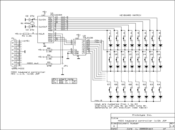
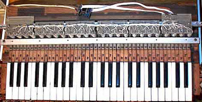
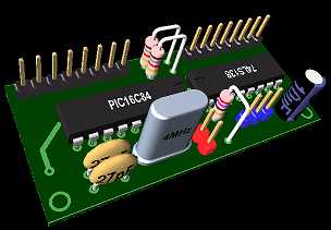
The schematic design is based on most popular PIC16F84 (or PIC16C84) single-chip controller by Microchip. It supports up to 64 keys without velocity sensing. I used keyboard from an old analog instrument, just adding a swich under every key and wiring swiches to connect them as shown on schematic below.
Schematic:
Used
parts:
U1:
PIC16F84. Can be used PIC16C84. The difference is that the first one
has Flash memory, and the second has EEPROM memory. There is no difference
in way they are used in such designs.
U2:
74LS138. This is TTL decoder 3:8 used for key rows scanning.
Q1:
Quartz resonator. Must be 4MHz.
C2,C3:
Capacitors 27pF each. Certain quartz resonators have these capacitors
integrated. If
you use such resonator, there is no need of C1 and C2.
R1..R3:
Resistors 1..10 k. Used to hold up certain IC pins. I use 1.8 k.
R3:
Resistor 270 Ohms to protect MIDI output from shortcut.
Diodes:
Each key has serially connected diode to prevent keycrossing when more
than one key is pressed on keyboard. These can be any type of standard
diodes.
P1:
An DB15 male connector.
JP1:
Jumper or moment action Button, depending on HEX file version.
Embedded
software:
It
is NOT enough to build this schematics in order to use it. An necessary
part is embedded program. I wrote it using Mpasm by Microchip.
I put here the hex code produced by Mpasm (this is ready to use object
code). By clicking on coloured text you can download whole
project (basic version) along with some additional information
and programs.
During the project developing a number of consequent versions of HEX
files have been released. The list of these versions is given below.
Clicking on list items you can download selected versions (in zip format).
Downloaded archive files contain explanations text file, hex file and
schematic diagram of device.
You'll need a PIC programmer in order to burn the HEX file into PIC.
The programmer is very simple and easy-to-make unit. The first
programmer I used is here (ZIP),
the one I'm using now is here (PDF).
MKC
VERSIONS:
- Basic Version (oldest)
-
Version 1.54 (newest)
Some of downloaded files (PDF format) require Adobe Acrobat Reader. You can download it for free by clicking on the link above or the banner below.
![]()
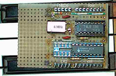
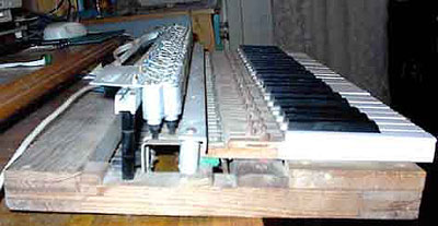
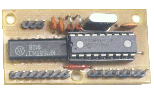
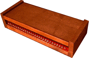
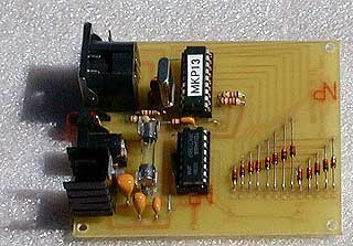
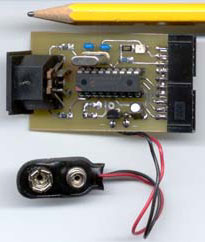
Construction:
Here you
can see pictures of MKC prototype and my first keyboard. Nothing
more to say...
You made it:
Some
of realizations of MKC made by you are shown below. All materials
are published under kindly agreement of their authors. Publishing these
materials could help more people to build and use MKC.
NOTE:All designs shown below will work
using original firmware published on this site (see Embedded
software ).
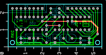
Igor
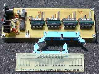
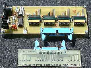
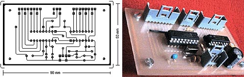
Popov from Ukraine (his
site here) developed nice printed circuit board (PCB) using OrCad
package under DOS. Pictures below show photo and screenshot of PCB design.
More detailed graphic files about Igor's PCB design could be downloaded
from here. Schematic files are included
in order to track changes made in parts names. Thanks, Igor.
The
next passion of Igor is VRML (Virtual Relity Modelling Language). Here
is an projection of his 3D model of the PCB shown above.
More things about Igor's work and VRML can be found on Igor's sites:
The VRML demo can be downloaded directly from Igor's site here. If would require VRML plug-in installed in your browser. Plug-ins and many other things about VRML modelling can be found here (site in Russian).
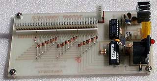
Vern
Jones from USA (his
site here) developed his project using Visio package. His design
supports PC soundcard and standard MIDI devices as well. Shown is photo
of Vern's design. You can download the full files set from here.
Schematic file is included.
Vern has also kindly provided original documentation of his design in
DOC (M$ Word) format. You can download it from here.
There are all graphic originals of PCB's and schematic descriptions.
The documents
for these PCBs can be printed thru M$ Word on a lazer or inkjet
printer. They will print out in the correct scale (1:1) on clear mylar
to make direct photo boards. Thanks, Vern.
Vern also provided a picture of his Rodgers Trio organ. He added MIDI scanners based on MKC to organ's Middle manual and Pedalboard. Similar scanners will be added to Upper and Lower keyboards also and maybe one more for scanning tab stops (the red and white bars seen on picture). I'm proud with MKC working good in this nice instrument. Thanks again, Vern :-)
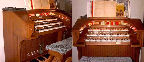
Here is Vern's Pedalboard Controller used in his organ:
Continuing development of this line of units, Vern also made Stop Tab/Switch Controller unit for controlling famous Ahlborn Archive classic organ emulator. This design was also based on MKC.
That is how the ready Ahlborn control unit looks outside:
You
may order the units shown here directly from Vern.
More information can be found on Vern's
site. Here is functions
table for this unit (zipped Excell'97 worksheet).
Pedalboard Controller and Stop Tab/Switch Controller were ordered and assisted by Jerry Cluff, another MIDI/pipe organs dedicated person. You may find more information about ordering/purchasing these units and many more organ related goodies on Jerry's site. Here is the second one of his sites.
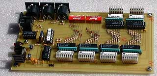
Here are two more Pedalboard Controllers - 13 and 25 pedals.
Another popular MIDI expander - D110 by Roland has its Stops Control Unit, based on custom version of MKC, thanks to Vern again. Here si how it looks:
It can control up to 4 D110 units, set on different MIDI channels.
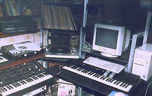
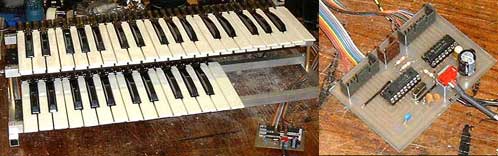
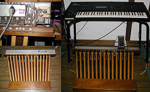
Nik 'Rebuzz' from Russia embedded MKC into his second (5 octaves) keyboard . Here is a picture of his studio. MKC based keyboard is the one below the computer keyboard. Thanks, Nik.
Paolo Airasca from Italy started his own modular keyboard scanner design. CPU unit based on MKC is shown here. The decoder chip (74LS138) is placed on another PCB, built-in in the keyboard unit for cabling minimizing. This kind of design is very flexible. It allows expanding the system by adding similar keyboard units and replacing only the CPU unit with more capable one (mkc128 or upper). Thanks, Paolo.
Gerrit Lammertink from Netherlands (his site here) built his own 5 octave MIDI keyboard based on MKC, using parts of an old electronic organ. Here you can find full information on his keyboard (pictures, schematic, PCB, instructions etc.). Thanks, Gerrit.
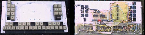
Here is another project of Gerrit made by old PC keyboard plus MKC unit. Gerrit added chord keys besides the normal keys. Chords keys are 'hard wired' to a number of major chords that can be played by clicking single chord key in accordion-like way. Thanks Gerrit for giving me the idea about adding chords implementation in MKC project.
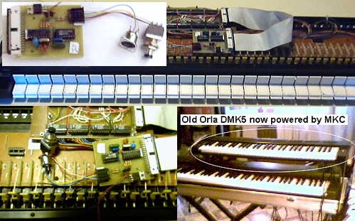
Marco Tavan from Italy recovered an old 61 keys Orla DMK5 keyboard for using it with B4 Hammond organ emulator software by Native Instruments. Marco used MKC plus additional multyplexer, in order to use standard common rail keying instead matrix keying. Bravo, Marco.
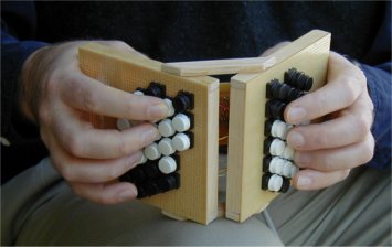
Here is an interesting gadget whose hardware design is based on MKC. Paul Everett (his site here) wrote his own firmware for this. You can design such device using Paul's software as well as MKC native firmware. The original instrument that inspired this project was named Hayden Duet Concertina. I've never heard about it before but does this have a matter :-)
Ron Fleming got a pedalboard from an old Lowery Organ and after redesigning its contact system and adding MKC, here is how his rig looks. Thanks, Ron.
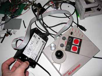
Pierre from France has built another exotic MIDI controller incorporating MKC in Nintendo game pad. Here is the picture.
If you have made your version of MKC and want to place here its photo, just e-mail me .
Future:
There are a lot of ideas about how to continue developing this project. The first is to make it Velocity sensitive. There are some ideas about it, especially I like the idea given by Paul Read. Unfortunately, there is an nasty RAM limitation imposed by the PIC chip (there are 64/36 RAM bytes only) which don't allow me to make software Velocity implementation. Anyway, I continue thinking about it... There are other Microchip products which have much more RAM. Let me see the prices.
The
main purpose of publishing this project is to give an easy way for
everyone to build his own MIDI keyboard using ready keyboard pad from
an old instrument. Information placed here is enough for more of readers
to make the project without any additional help. Unfortunately, buying
parts from the store is not enough for building the project. An PIC programmer
with software is also required in order to burn supported HEX files into
PIC.
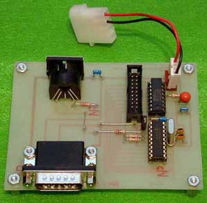
If, by some reason, you are not able to buy/program PIC16F84, you can
order it. You can also order DIY (do-it-yourself) kit or ready
assembled and tested unit like this:

Unit code for this item is MKC. Click here or here to see ordering details.
Thanks, guys!
I'd like to mention the people who gave me some help and ideas about this project:
- To my friend
Emil
Raynovski who opened my eyes for MIDI protocol and for the
pleasure of discussing the schematics and embedded program.
- To my coleague Luchezar Georgiev for suggestions he made for avoiding problem with key-crossing. Go to his page to see his project MIDI filer.
- To Paul Read for giving me some ideas about adding Velocity sensing to the keyboard.
- To Igor Popov for developing a PCB (printed cirquit board) for this keyboard controller also for reporting me an error in schematic drawing (now fixed). Go to his site to see his projects.
- To Ron Fleming for introducingthe fabulous B4 software by Native Instruments that inspired me to design drawbar encoder units (mdbc8x9 and mdbc16x9) and the much more complicated B4 console encoder (B4ce)
Questions
and Answers:
Here
are some of interesting questions I'm receiving about this project along
with my answers.
Q:
I have problems
while trying to connect MKC to my AWE soundblaster. It does not
seem to receive MIDI messages. What should I do?
A: I've
been notified about this problem by a number of people that are using
MKC. Nik 'Rebuzz'
found the answer. It appeared that AWE has serial resistor connected between
the power supply line coming from motherboard's slot to pins #1,#8 and
#9 (+5v) on MIDI/Game connector. This resistor probably limits the current
that is drawn by MKC from MIDI/Game port (remember: the original
MKC is powered directly by the port and draws about 10mA from there).
Nik just short-cutted this resistor, soldering a wire directly on the
soundblaster's PCB. And that was all. Thanks, Nik.
Q:
I use a
soundcard which don't recognize standard 'NoteOff' message. Instead,
it recognises 'NoteOn' (Velocity=0) like 'NoteOff'. Can
MKC support 'NoteOn' (Velocity=0) message instead 'NoteOff'?
A: Yes,
version 1.54 supports both 'NoteOff' message
types. User decides which kind of 'NoteOff' message will be generated
during playing.
Q: Is
it possible to send 'ChangePreset' and 'ChangeBank' messages
using the same design of keyboard?
A: Yes,
version 1.54 includes mkcc154.hex
which supports 'ChangePreset' and 'ChangeBank' commands.
Q: I
mentioned that controller generates 'AllNotesOff' message every
time when the last key was released. What is the need of such feature?
Is there a way to walk arould it?
A: The
purpose of this feature was to avoid note hanging on cheaper soundcard
due to missing 'NoteOff' message. Now a new hex file is added wich
supports all mkcc2.hex
features excluding 'AllNOtesOff' message generating during
playing. The filename is mkcc151.hex. Also
file mkcc152.hex
was added wich allows user to decide at runtime wether 'AllNotesOff'
message will be generated or not. You could download mentioned files from
here.
Q:
Can MIDI
channel be changed at runtime?
A: Now
it is possible. I just uploaded new HEX file to the site which allows
user to cnahge at runtime MIDI channel, Starting octave, Starting note
and default Velocity. No hardware changes are required except changing
JP1 jumper with pushbutton. Go get it.
Q:
Many questions.
THE
BIG ANSWER:
To answer the most of questions about making MIDI controllers I wrote
an article, dedicated
to practical aspects of MIDI technology. There are a number of documents
concerning MIDI and electronics in my documents
page.
Q:
How to make keyboard to start with MIDI note #36 (C - Do)?
A: It
is now possible to use this design to drive keyboard starting at MIDI
note #41 (F-Fa), or keyboard starting at MIDI note #36 (C-Do). The only
difference is the status of JP1 jumper (see JP1 table on schematic drawing).
Q:
Can I use this keyboard with standard MIDI stuff (non PC)?
A:
In order to use the keyboard as standard MIDI device you should buy (or
build) a power supply unit (5V stabilized),
also build an buffer module like one described here
(in Hardware projects). CAUTION:If
you have no good background in electrics and electronics, do not try to
build these units (especially the power sullpy unit)! Besides the risk
of destroying expensive MIDI stuff, an electrical shock could be fatal
for your life and health !!!
Q:
Can I use PIC16F84 instead PIC16C84 shown on schematics?
A:
Yes (read the Used parts section), PIC16F84 is full functional analog
of PIC16C84. The difference between them is that the second one is based
on EEPROM memory while the first - on FLASH memory. There is no difference
in programming/using these chips.
Q:
Can I order pre-programmed chip by mail?
A:
Pre-programmed chip or even ready-made MKC unit can be ordered
here.
Q:
Can I use quartz resonator at 6MHz instead 4MHz?
A:
No, you can't. Technically, using such quartz you'll not damage the controller
nor controlled MIDI device, but in order to respect timing intervals required
by MIDI specification you have to use an quartz resonator working at exactly
4MHz in this design.