project
#5: MKC128
128 scanpoints MIDI Keyboard Controller
This unit is available thru www.midiboutique.com
Description:
An
complicated variant of MIDI controller descended from my MIDI
keyboard project. Supports up to 128 keys. Actually keyboard
matrix consists of 16 rows and 8 columns (128 scanpoints). The function
of every scanpoint is user-defined. Go to
embedded software in order to learn how to define
Controller Functions Table. This way any
user-defined configuration is possible to be made using the same hardware
design and only re-defining scanpoints functions.
Examples:
1.128
keys keyboard with no additional control functions, divided into two 64-keys
divisions, each generaing NoteOn/NoteOff messages on different MIDI channel;
2.124
keys keyboard divided in two 62-keys divisions, each generating NoteOn/NoteOff
messages on different MIDI channel and having its own Transposer;
3.61
keys keyboard and 32 keys pedalboard generating NoteOn/Off messages on
different MIDI channels, Coupler Upper-to-Pedal, Transposers for both
divisions, 4 discret drawbars assigned to certain Control Change messages;
4.64
keys keyboard with 8 drawbars (each has 9 positions), working on fixed
MIDI channel.
5.128
contacts control board for controlling MIDI module (for example Ahlborn
Archive module).
6.16*6=96
fret contacts for stringless MIDI guitar neck + 6 string trigger points
(all 112). Events for each string transmitted on different MIDI
channel, playing different instrument(wow, this should be a whole orchestra,
expect a new project here).
Etc, etc.
ANY configuration is possible to be done. The main limit is scanpoints
number (up to 128).
Two complete examples of user-defined Controller Functions Table can be
found in embedded
software section.
Schematic:
(click
on schematics to see them enlarged)
first variant, using single decoder 74LS154
(obsolette) 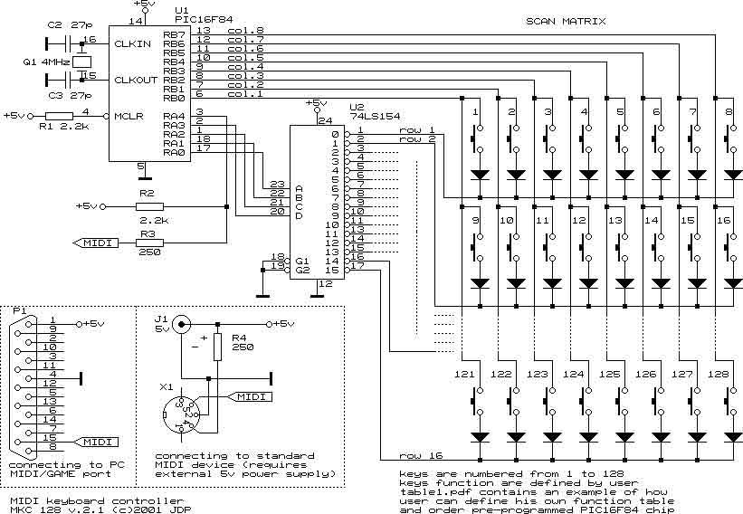
second
variant, using decoder 74LS138
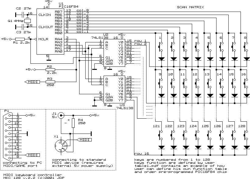
NOTE:
both variants are functionally identical and run under the same firmware.
Used
parts:
U1:
PIC16F84. Can be used PIC16C84. The difference is that the first one has
Flash memory, and the second has EEPROM memory. There is no difference
in the way they are used in such designs.
U2(in
first variant):74LS154
decoder 4:16 used for rows scanning.
U2,U3
(in second variant):74LS138 decoders
3:8 used for rows scanning.
Q1: Quartz
resonator. Must be 4MHz.
C1,C2:
Capacitors 27pF each. Certain quartz resonators have these capacitors
integrated. If
you use such resonator, there is no need of C1 and C2.
R1,R2:
Resistors 2.2k. Used to hold up certain IC pins.
R3,R4:
Resistors 250 Ohms to limit output current to 10 mA.
Diodes:
Each contact (key) in scanmatrix has serially connected diode to prevent
keycrossing when more than one contact is closed (a few keys pressed on
keyboard). These can be any type of standard diodes.
P1: An
DB15 male connector. Used for connecting mkc128 to PC Game/Joystick
connector.
X1: An
DIN 5 female connector. Used for connecting mkc128 to standard
MIDI device.
NOTE: The standard MIDI device must have an opto-isolated
input. This is an standard requirement for every MIDI input. The mkc128
MIDI output is capable to drive an opto-isolator with up to 10 mA wich
is the standard current for MIDI interface. Click here
for more information about interfacing MIDI devices.
J1:
Female connector for using external +5v stabilized power supply. Used
when mkc128 is connected to standard MIDI device.
NOTE: Using external power adaptors with
output voltage more than 5v could damage your controller and the other
MIDI devices connected to it. As I know there are no 5v adaptors on the
mass market. Making such adaptor is relatively simple work. You can click
here to obtain such adaptor schematic.
It is not required to be an electrician in order to make such adaptor
but a basic knowledge about electrical safety is a must. I assume
that reading this means that you are capable to build the schematic shown
above, thus you are capable to build the adaptor yourself.
The only way to have this controller is ordering pre-programmed chip. Since this is dfm, no HEX file will be published here. The controller is fully customizable, so the functions of pre-programmed chip should be defined by you using simple table form (Controller Functions Table). This way you could define whatever MIDI controller you want, using the same hardware design (the same PCB). Two examples of user-defined Controller Functions Table can be found here:
To view these examples, you'll need Adobe Acrobat Reader. Click on the banner below to install Reader on your system.
![]()
Real versions of Controller Functions Table, defined by customers, can be found below where their devices are shown.
How MKC128 looks:
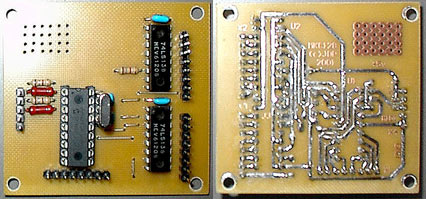
These are top and bottom view of assembled mkc128 controller. The shown one is based on the second schematic variant, using two 74LS138 decoders. You may order assembled and tested controller like this or kit for assembling it (including all parts, PCB and User Manual).
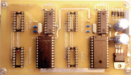
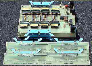
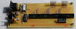
Paolo Airasca from Italy developed dual MIDI encoder based on mkc128 (first schematic variant using 74LS154 decoder) for controlling two keyboards, one pedalboard and 64 additional stops (control switches). Here is how Paolo's PCB looks:
Vern Jones from USA is developing a line of control units for Ahlborn Archive classic organ emulators. The one shown here, based on mkc128, is designed in colaboration with Jerry Cluff (USA). Here are the links so their sites:
Rasko Antanaskovic from Yugoslavia made his MIDI accordeon based on custom version of mkc128.
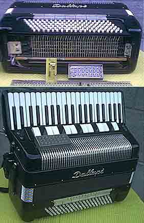
mkc128 PCB can be seen at the bottom of upper picture where dis-assembled accordeon is shown. Here is the Controller Functions Table defined by Rasko for this instrument.
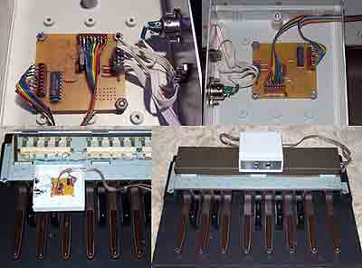
Lynn
Walls from USA embedded mkc128 into his
nice Hammond Pedal board.
Here are the pictures made during assembling the unit:
And here is the pedal board itself:
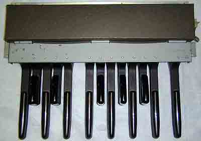
Here is the Controller Functions Table defined by Lynn for this device.
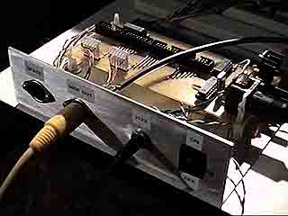
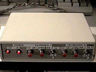
Recently, Vern Jones used a custom version of mkc128 in building 2-manual MIDI-organ console out of two broken Fatar SL-161 keyboards. Initially, the owner of Fatar's intended to use 2 mkc controllers plus Merger unit. But he found much more elegant and inexpensive way: using single mkc128 instead. Go call Vern, he really knows how to do such things. Here are shown the both units he made for this design: keyboard encoder that is embedded into consolle and the control unit that is designed in separate box.
Here is another Vern's product - 25 pedals encoder, based on mkc128 custom version. This unit supports some additional functions like Octave Transposition in both directions, Sustain, All Notes Off (Cancel) button, MIDI channel selector:

The owner of the 2-manual MIDI-organ console described above, Simone Ghetti also sent me link to his project's site. You can find there more details about his beautiful instrument. Here is the main view of it:
Future:
The next version should scan 16*16=256 scanpoints matrix. It will be convenient for using in four-parted keysets (2 Manual, 1 Pedal keyboard, 1 Control keyset), each up to 64 points. As I know the most standard organ keyboard are divided this way. The control keyset consists of a number of buttons and discret drawbars used for controlling synthesizer parameters.
Details about ordering this and and other units can be found here. Package for this unit includes User Manual with fully documented schematic and Controller Functions Table as defined by Customer.