project
#9: B4ce
B4 console encoder
This unit is available thru www.midiboutique.com
Description:
When
I saw B4 demo for the first time, I beloved it (thanks to Ron
Fleming). B4
(by Native
Instruments) is nice software Hammond organ
emulator, combining perfect graphic design with perfect sound design.
The purpose of B4ce project is to create physical console from
scratch for controlling B4.
The original console (B4 Keyboard View):
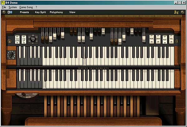
has two manuals, each 61 keys, one pedalboard - 25 keys, 9 drawbars for upper keyboard, 9 drawbars for lower keyboard, 6 drawbars for pedalboard and a number of discrete/analog controls for different parameters. Some of controls are not shown on the picture. They are placed in B4 Control View:
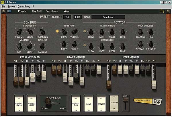
Some
of controls of Keyboard View are doubled on Control View for convenience.
The B4ce controller itself is designed to be able to scan 4 separate
scanmatrices, each 64 scanpoints (for scanning keyboards and switch/select
controls), plus 48 potentiometers (drawbars and continuous controls).
The assignment table of scanpoints/potentiometers is
shown below the schematic.
Schematic:
(click
on schematic to get picture enlarged)

Used
parts:
U1:PIC16F874/PIC16F877.
U2..U5:74LS138
decoder 3:8.
U6..U11:4051
1-to-8 analog multyplexer.
Q1: Quartz
resonator (crystal). Must be exactly 20MHz.
C1,C2:
Capacitors 27pF.
R1: Resistor
2.2 kOhm.
R2,R3:
Resistors 220 Ohm.
R4:
Resistor 2.2 kOhm.
R5: Resistor 100 Ohm.
B1: Momentary
action button.
X1: DIN
5 female connector.
Diodes:
Generic Si diodes.
Potentiometers:
10 kOhm, linear. Some sliding, some rotary, depending on their function
and your preference. In case when real drawbars (9 position sliding switches)
are used, they could be connected instead drawbar potentiometers this
way:
The power supply should be stabilized +5V/1A (like the one described here). The pin #14 of U1 and pins #16 of U2..U11 are connected to Vcc (+5V wire), the pin #5 of U1 and pins #7,8 of U5..U11 are connected to common (ground) wire. These pins are not shown on schematic.
|
Scan-point/
pot |
B4
Function
|
MIDI
Function/
Channel |
Contact
kind
|
Visual
control
|
|
Scan matrix 1 - Upper keyboard
|
||||
|
1
|
Key 1 |
Note 36/1
|
Momentary
contact
|
 |
|
2
|
Key 2 |
Note 37/1
|
Momentary
contact
|
|
|
...
|
...
|
...
|
...
|
|
|
61
|
Key 61 |
Note 96/1
|
Momentary
contact
|
|
|
62
|
Key 62 |
Note 97/1
|
Momentary
contact
|
|
|
...
|
... |
...
|
...
|
|
|
64
|
Key 64 |
Note 99/1
|
Momentary
contact
|
|
|
Scan
matrix 2
- Lower keyboard
|
||||
|
1
|
Key 1 |
Note 36/2
|
Momentary
contact
|
 |
|
2
|
Key 2 |
Note 37/2
|
Momentary
contact
|
|
|
...
|
...
|
...
|
...
|
|
|
61
|
Key 61 |
Note 96/2
|
Momentary
contact
|
|
|
62
|
Key 62 |
Note 97/2
|
Momentary
contact
|
|
|
...
|
... |
...
|
...
|
|
|
64
|
Key 64 |
Note 99/2
|
Momentary
contact
|
|
|
Scan
matrix 3
- Pedal board
|
||||
|
1
|
Key 1 |
Note 36/3
|
Momentary
contact
|
 |
|
2
|
Key 2 |
Note 37/3
|
Momentary
contact
|
|
|
...
|
...
|
...
|
...
|
|
|
25
|
Key 25 |
Note 60/3
|
Momentary
contact
|
|
|
26
|
Key 26 |
Note 61/3
|
Momentary
contact
|
|
|
...
|
... |
...
|
...
|
|
|
64
|
Key 64 |
Note 99/3
|
Momentary
contact
|
|
|
33..64
|
not used
|
...
|
...
|
...
|
|
Scan
matrix 4 - Switches and Selectors
|
||||
|
1
|
Vibrato Lower switch |
Control Change 30/1
|
2
position switch
|
 |
|
2
|
Vibrato Upper switch |
Control Change 31/1
|
2
position switch
|
|
|
3
|
Percussion switch |
Control
Change
66/1
|
2
position switch
|
 |
|
4
|
Overdrive switch |
Control
Change
67/1
|
2
position switch
|
|
|
5
|
Rotator switch |
Control
Change
68/1
|
2
position switch
|
|
|
6
|
Velocity switch |
Control
Change
69/1
|
2
position switch
|
|
|
7..8
|
not
used
|
...
|
...
|
...
|
|
9
|
Vibrato/Keyclick
selector, pos.V-1
|
CC73(V127)/1 |
6
position switch
|
 |
|
10
|
Vibrato/Keyclick
selector, pos.C-1
|
CC73(V0)/1
then CC74(V0)/1 |
||
|
11
|
Vibrato/Keyclick
selector, pos.V-2
|
CC73(V127)/1 |
||
|
12
|
Vibrato/Keyclick
selector, pos.C-2
|
CC73(V0)/1
then CC74(V64)/1 |
||
|
13
|
Vibrato/Keyclick
selector, pos.V-3
|
CC73(V127)/1
then CC74(V127)/1 |
||
|
14
|
Vibrato/Keyclick
selector, pos.C-3
|
CC73(V0)/1
then CC74(V127)/1 |
||
|
15..16
|
not
used
|
...
|
...
|
...
|
|
17
|
Preset
Bank selector, pos.1
|
Program
Change 0..119/1 (combined with Master Preset Bank selector position)
|
10
position switch
|
 |
|
18
|
Preset
Bank selector, pos.2
|
|||
|
19
|
Preset
Bank selector, pos.3
|
|||
|
20
|
Preset
Bank selector, pos.4
|
|||
|
21
|
Preset
Bank selector, pos.5
|
|||
|
22
|
Preset
Bank selector, pos.6
|
|||
|
23
|
Preset
Bank selector, pos.7
|
|||
|
24
|
Preset
Bank selector, pos.8
|
|||
|
25
|
Preset
Bank selector, pos.9
|
|||
|
26
|
Preset
Bank selector, pos.10
|
|||
|
27..32
|
not used |
...
|
...
|
...
|
|
33..44
|
Master Preset selector |
Program Change 0..119/1 (combined with Preset Bank selector position)
|
12
position switch
|
 |
|
45..48
|
not used |
...
|
...
|
...
|
|
49..60
|
Lower Preset selector |
Program
Change 0..119/2 (depends
on Preset Bank selector position)
|
12
position switch
|
 |
|
61..64
|
not used |
...
|
...
|
...
|
|
Potentiometers
|
||||
|
1
|
Drawbar 1 (16'), Upper |
Control
Change
12/1
|
sliding
potentio-meters
|
 |
|
2
|
Drawbar 2 (5 1/3'), Upper |
Control
Change
13/1
|
||
|
3
|
Drawbar 3 (8'), Upper |
Control
Change
14/1
|
||
|
4
|
Drawbar 4 (4'), Upper |
Control
Change 15/1
|
||
|
5
|
Drawbar 5 (2 2/3'), Upper |
Control
Change
16/1
|
||
|
6
|
Drawbar 6 (2'), Upper |
Control
Change
17/1
|
||
|
7
|
Drawbar 7 (1 3/5'), Upper |
Control
Change
18/1
|
||
|
8
|
Drawbar 8 (1 1/3'), Upper |
Control
Change
19/1
|
||
|
9
|
Drawbar 9 (1'), Upper |
Control
Change 20/1
|
||
|
10
|
Drawbar 1 (16'), Lower |
Control
Change
21/1
|
sliding
potentio-meters
|
 |
|
11
|
Drawbar 2 (5 1/3'), Lower |
Control
Change
22/1
|
||
|
12
|
Drawbar 3 (8'), Lower |
Control
Change
23/1
|
||
|
13
|
Drawbar 4 (4'), Lower |
Control
Change
24/1
|
||
|
14
|
Drawbar 5 (2 2/3'), Lower |
Control
Change
25/1
|
||
|
15
|
Drawbar 6 (2'), Lower |
Control
Change
26/1
|
||
|
16
|
Drawbar 7 (1 3/5'), Lower |
Control
Change
27/1
|
||
|
17
|
Drawbar 8 (1 1/3'), Lower |
Control
Change
28/1
|
||
|
18
|
Drawbar 9 (1'), Lower |
Control
Change
29/1
|
||
|
19
|
Drawbar 1 (16'), Pedal |
Control
Change
33/1
|
sliding
potentio-meters
|
 |
|
20
|
Drawbar 2 (5 1/3'), Pedal |
Control
Change
34/1
|
||
|
21
|
Drawbar 3 (8'), Pedal |
Control
Change
35/1
|
||
|
22
|
Drawbar 4 (4'), Pedal |
Control
Change
36/1
|
||
|
23
|
Drawbar 5 (2 2/3'), Pedal |
Control
Change
37/1
|
||
|
24
|
Drawbar 6 (2'), Pedal |
Control
Change
38/1
|
||
|
25
|
Expression pedal |
Control
Change
11/1
|
rotary
potentio-
meter |
 |
|
26
|
Rotary speed |
Control
Change
1/1
|
rotary
potentio-
meter |
 |
|
27
|
Percussion Volume |
Control
Change
70/1
|
rotary
potentio-meters
|
 |
|
28
|
Percussion Decay |
Control
Change
71/1
|
||
|
29
|
Percussion Harmonic |
Control
Change
72/1
|
||
|
30
|
Vibrato Mix |
Control
Change
73/1
|
rotary
potentio-meters
|
 |
|
31
|
Vibrato
Depth
|
Control
Change
74/1
|
||
|
32
|
Keyclick
Amount
|
Control
Change
75/1
|
||
|
33
|
Tube
Amp. Drive
|
Control
Change
76/1
|
rotary
potentio-meters
|
 |
|
34
|
Tube
Amp Volume
|
Control
Change
7/1
|
||
|
35
|
Tube
Amp Body
|
Control
Change
78/1
|
||
|
36
|
Tube
Amp Brightness
|
Control
Change
79/1
|
||
|
37
|
Rot.Sp.Treble
Tone
|
Control
Change
80/1
|
rotary
potentio-meters
|
 |
|
38
|
Rot.Sp.Treble
Slow Speed
|
Control
Change
81/1
|
||
|
39
|
Rot.Sp.Treble
Fast Speed
|
Control
Change
82/1
|
||
|
40
|
Rot.Sp.Treble
Accel.
|
Control
Change
83/1
|
||
|
41
|
Rot.Sp.Bass
Tone
|
Control
Change
90/1
|
rotary
potentio-meters
|
 |
|
42
|
Rot.Sp.Bass
Slow Speed
|
Control
Change
91/1
|
||
|
43
|
Rot.Sp.Bass
Fast Speed
|
Control
Change
92/1
|
||
|
44
|
Rot.Sp.Bass
Accel.
|
Control
Change
93/1
|
||
|
45
|
Mic.Treble/Bass
Balance
|
Control
Change
8/1
|
rotary
potentio-meters
|
 |
|
46
|
Microphone
Pan
|
Control
Change
10/1
|
||
|
47
|
Microphone
Spread
|
Control
Change
9/1
|
||
|
48
|
Microphone
Distance
|
Control
Change
3/1
|
||
NOTES:
- All numbers shown
in the table are decimal.
- MIDI channels are
numbered 1..16.
- For some Continuous
Controllers the controller Value is given in braces, for example: CC73(V127)/1
means Continuous controller #73, Value 127 on chanel #1.
-
All coloured functions are really supported by B4ce and B4 regardless the fact that they are not visually supported by B4. During tests B4 covered whole MIDI note range (128 notes), regardles the fact that on-screen keyboards are 61/61/25 keys. Thus, physical console based on B4ce can have more keys (64/64/64) than visual one.
-
While testing B4 demo with my MIDIex software I found that presets (inverted coloured keys) are controlled by MIDI Program Change messages as follows:
-
Program Change #0..23 on channel 1 affects Upper keyboard presets (actually these are a kind of master presets which affect Upper, Lower keyboard and Pedalboard simultaneously) along with Presets Bank selector:
There are virtually 10 banks (120 presets), but only banks #1 and 2 (24 presets) are supported by B4 demo version.
-
Program Change #0..23 on channel 2 affects the Lower keyboard and Pedalboard presets only.
-
More notes:
- There are few free scanpoints in scanmatrix #4 which can be used for further developed B4 functions (I hope Native Instruments will continue it).
- The kind of potentiometers suggested in table is not obligatory. For instance, you can use rotary potentiometers for drawbars. But this would be away from original design and instrument feeling.
- It turned out that B4 have also Velocity sensing. B4ce project does not support velocity sensitive key contacts. Adding velocity sensing would require more than one PIC chips to be involved. But this is a brand new project...
- Thanks Siew Hung Shum from Singapore for helping me with Vibrato/Keyclick amount controller. And much more...
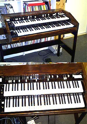
- Are you curious about how is B4ce unit looking? Here it is:

Some custom realizations of B4 organs using B4ce encoder are shown below. All materials are published under kindly agreement of their authors.
- Wolfgang Deffner from Germany made an mini-version of B4-based Hammond organ. More details can be found on his B4-controller site.
- Claudio Zulian from Italy built his B4 using an old Nord-Electro 2-manual keyboard.
The only way to have this controller is ordering pre-programmed chip or assembled and tested unit. Since this is dfm, no HEX file will be published here.
Details
about how to order pre-programmed chip or ready made unit can be found
here.
The package includes B4ce init and User Manual with fully documented
schematic and MIDI Implementation Table,and doesn't include key contacts,
switches, diodes and potentiometers.