project
#4: MDBC8x9
MIDI Drawbar 8*9 Controller design
Description:
This
controller is based on Project#1 (MKC).
Instead keyboard keys here are scanned 8 drawbars each with 9 positions
(from 0 to 8). I developed this controller by idea of Ron
Fleming. Ron asked me to re-design my MIDI keyboard controller in
such way that he could use it for drawbar setting of famous B4
software Hammond organ emulator by Native
Instruments. Instead Note On and Note Off messages this
controller generates MIDI Control Change messages at MIDI channel
#1 as follows (Table 1):
| Table 1: MIDI Controllers supported | ||
|
Drawbar
#
|
MIDI
Control #
|
Control
name
(by General MIDI specification) |
|
1
|
12 ($0C)
|
Undefined
|
|
2
|
13 ($0D)
|
Undefined
|
|
3
|
14 ($0E)
|
Undefined
|
|
4
|
15 ($0F)
|
Undefined
|
|
5
|
16 ($10)
|
Undefined
|
|
6
|
17 ($11)
|
Undefined
|
|
7
|
18 ($12)
|
Undefined
|
|
8
|
20 ($14)
|
Undefined
|
Actually, each of drawbars is 9-position switch. Standard drawbar set
consists of 9 drawbars, like the well-known Voce drawbar controller:
Supporting 8 switching drawbars is only the first step of making drawbar
controller just by redesigning MKC software.
I intend to make next version of controller supporting 3x9=27 continuous
(potentiometer type) drawbars.
As far as we have switching drawbars here, we should define drawbar positions
mapping over MIDI Control value. Mapping is shown in Table2.
| Table 2: Drawbar positions mapping | |
|
Drawbar
position #
|
Mapped
Controller Value
|
|
0(off)
|
000 ($00)
|
|
1
|
010 ($0A)
|
|
2
|
030 ($1E)
|
|
3
|
045($2D)
|
|
4
|
060 ($3C)
|
|
5
|
078 ($4E)
|
|
6
|
099 ($63)
|
|
7
|
114 ($72)
|
|
8
|
127 ($7F)
|
These tables are firmware set and cannot be changed by user. Unlikely
mkc there is no way user
to change these parameters during operation. The only way to have different
settings for these tables is to order pre-programmed
chip from me. For details see Ordering.
Schematic:
(You can find more detailed
picture in project file.)
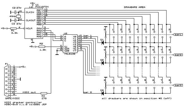
Used
parts:
U1:
PIC16F84. Can be used PIC16C84. The difference is that the first one has
Flash memory, and the second has EEPROM memory. There is no difference
in way they are used in such designs.
U2: 74LS138
decoder 3:8.
X1: Quartz
resonator (crystal). Must be 4MHz.
C1,C2:
Capacitors 27pF each. Certain quartz resonators have these capacitors
integrated. If
you use such resonator, there is no need of C1 and C2.
R1: Resistor
3.3 kOhms.
R2: Resistor
1.8 kOhms.
R3: Resistor
270 Ohms.
Diodes:
Can be any type of standard diodes.
P1: An
DB25 male connector for plugging into PC soundcard Game/MIDI port connector.
bar1..bar8:
9-position sliding switches (drawbar). rotary switches can also be used.
Embedded
software:
The
software (HEX file ready to burn into PIC) is contained in project
file. NOTE: HEX
file included here supports tables given above. If you want other
tables support you have to order pre-programmed
chip.
How MDBC8x9 could look:
Siew Hung Shum from Singapore developed his drawbar box (8 drawbars) based on mdbc8x9 project. Here is how the box looks:
Ron Fleming took an real drawbar set from Hammond organ, added mdbc8x9 and here is the result:

Future:
3*9 continuous (potentiomener type) drawbar controller is in my mind...
The project published here is free. But if you are not able to program chips, or want some custom versions of Table1 and Table2 to be programmed in, then you should order pre-programmed chip. Details about how to order pre-programmed chip for mdbc8x9, or kit or ready made unit can be found here.