The purposes of this tutorial are:
| To use this tutorial, you must copy the clip project into a convenient local project directory. If you have not already done so, follow the instructions in the Introduction on page 135 to obtain the example data. |
 Retrieve Model to load the wire file Tutorial2Set.wire.
Include Model to include the model Tutorial2Alian.wire.
Retrieve Model to load the wire file Tutorial2Set.wire.
Include Model to include the model Tutorial2Alian.wire.
This adds the model without deleting what was already there in the same way that loading a second file in Alias works.
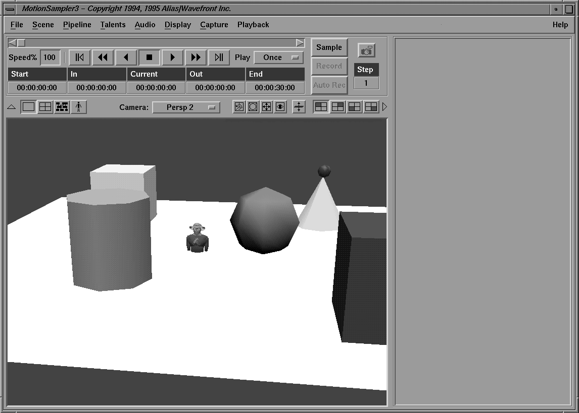
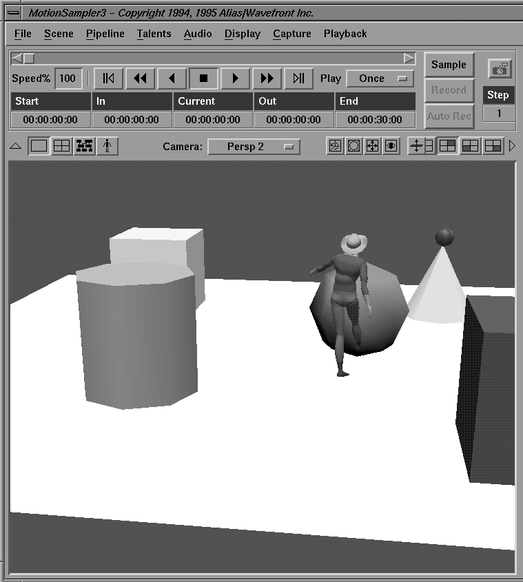
Notice that the character is embedded in the floor of the set. This is because the character was built around the origin, as was the floor. This problem is corrected later in this lesson with an Offset module.
The Biped2 filter and BipedTalent source modules are used to construct a pipeline to play back raw sample data on this character.
| Recall that modules are created by highlighting their names in the lists and then clicking the Use Module button, or by double-clicking on their names. |
| The DAGGroup filter has no inlets and the ImportXform source has no outlets. Both of these modules create their inlets and outlets as needed based on the specifications of the data files or their configurations. |
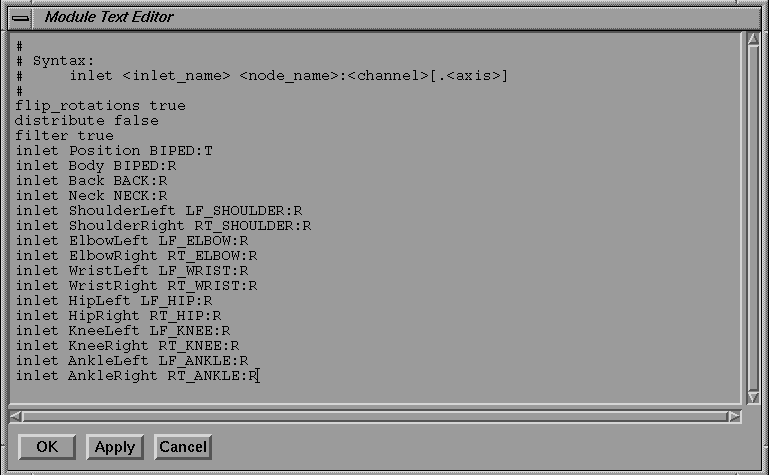
The syntax statement at the beginning is the usage statement for creating inlets and mapping them to dag nodes.
The <inlet_name> can be any text name, while the <node_name>:<channel>[.<axis>] must match an actual dag node in the file.
For example, the following specification:
inlet Neck NECK:R
creates an inlet called Neck whose data is placed on the rotation channels of the dag node named NECK in the wire file.
inlet Neck NECK:R.X
attaches the data only to the X rotation of the dag NECK.
The characters R, T, and S stand for rotation, translation and scale respectively, while the channel names X, Y, Z refer to the coordinate system.
| In one of the above cases, a 3 component connection is specified where in another case a single floating point connection is specified. These differences in data types are shown by the color of inlets and outlets in MotionSampler. |
The following describes how to create a series of inlets that map data to the standard dag names for the Biped2 filter. Although you have to type in these inlets, the data is saved with the filter when you save the pipeline.
| MotionSampler provides predefined modules that have built-in configuration files. These modules are listed as Predefined Modules in the lower right corner of the Module library lists. |
| Sinks are identified as K, sources as S, and filters as F. This predefined module matches what you have just typed in, and is provided as a convenience. |
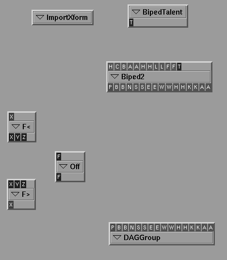
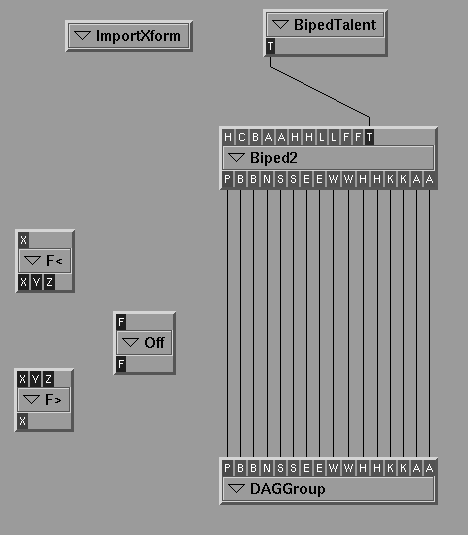
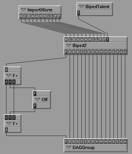
With the DAGGroup set up, the pipeline screen should resemble the following:
You can now connect the outlets of the Biped2 filter to the DAGGroup sink.
The inlets of the DAGGroup are carefully named to match the outlets of Biped2, so the connection process is quite straightforward. You can also connect the BipedTalent to the talent inlet on the Biped2 filter.
Try using Shift-drag and Ctrl-drag to connect these inlets and outlets so that they appear as follows:
Leave the FloatJoin, FloatSplit and Offset filters detached for now.
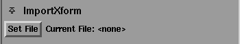
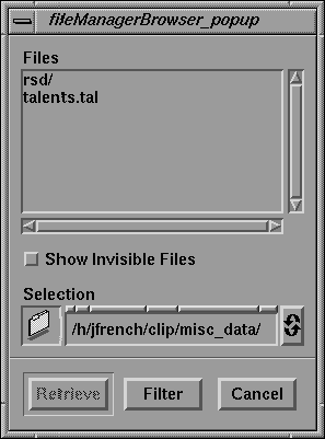
For the ImportXform source to define its inlets, you have to specify a filename for the module to read the raw data from.
The ImportXform area appears as follows:
Notice that no filename is specified at Current File.
Once you have selected a filename, the ImportXform source determines an appropriate set of outlets.
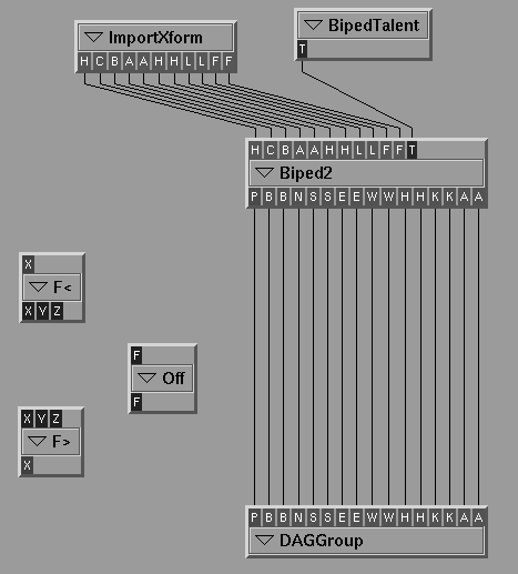
The pipeline is almost ready for execution.
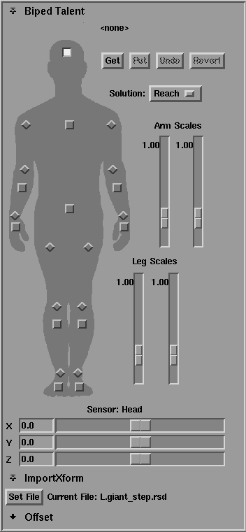
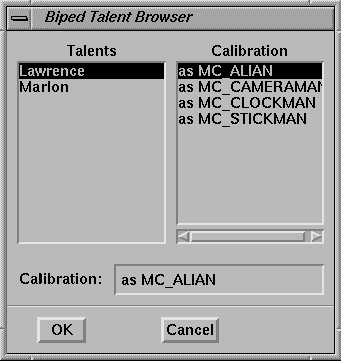
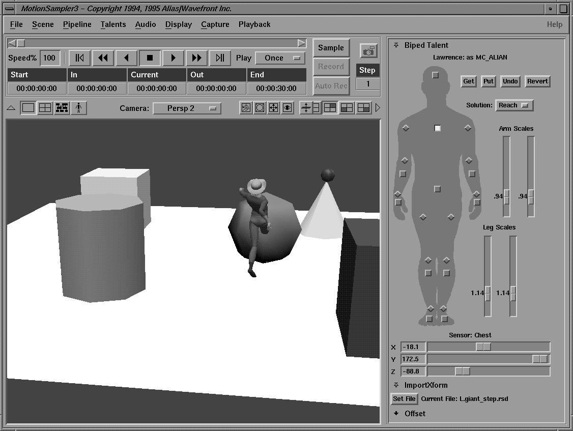
The BipedTalent loads the data from the calibration of the actor Lawrence as the character ALIAN. This way, many character's calibrations for a single actor can be stored together.
| The example raw motion sample files that were recorded with Lawrence as the actor are marked with an L, while those with Marlon are marked with an M. If you match the talent to the raw sample data, your results will be better. |
If everything has been connected correctly, the character will begin to move according to the raw sample file you chose earlier. You can use the interface to select other raw sample data if you want.
| You may need to adjust your view to see the character moving as follows: |
As you can see, the character is moving through the floor. The Offset module is used to raise the character above the floor.
Your pipeline should appear as follows:
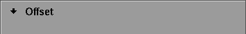
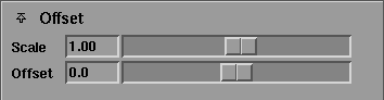
The Offset interface opens to show sliders for scale and offset as follows:
The character should appear as follows once you have adjusted the offset correctly:
This kind of real time adjustment is central to MotionSampler. You can also adjust the calibration values in real time as follows:
| Since the ImportXform source is reading raw sensor data, you can practice calibration (and learn the effects of the various controls) without the expense or complexity of running the motion capture gear. Several raw sample data files that contain calibration motions are provided. |