ms3or by click-dragging down the Utilities menu in Alias until you get to MotionSampler and then releasing the mouse button.
 Retrieve Model. A File Browser appears.
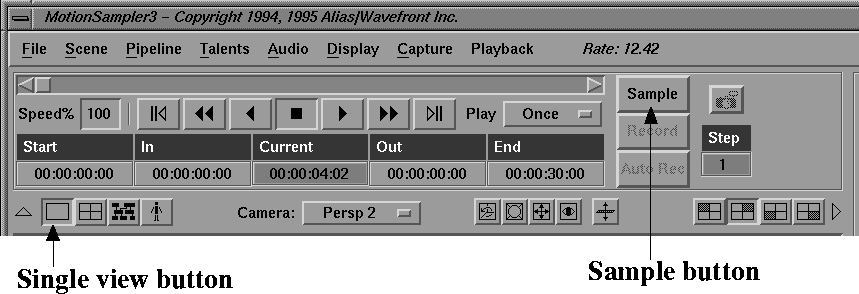
View Scene or click on the following button to switch to a single view:
Retrieve Model. A File Browser appears.
View Scene or click on the following button to switch to a single view:
| For more information about the View Controls, see the View Controls section earlier in this chapter. |
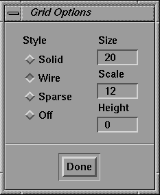
Grid Options....
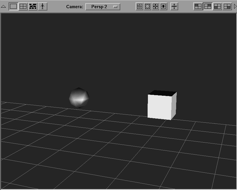
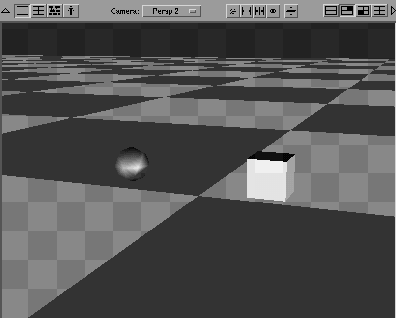
The Floor button appears as follows:
You can tell when you have the floor in the right position because it will intersect the cube and sphere as follows:
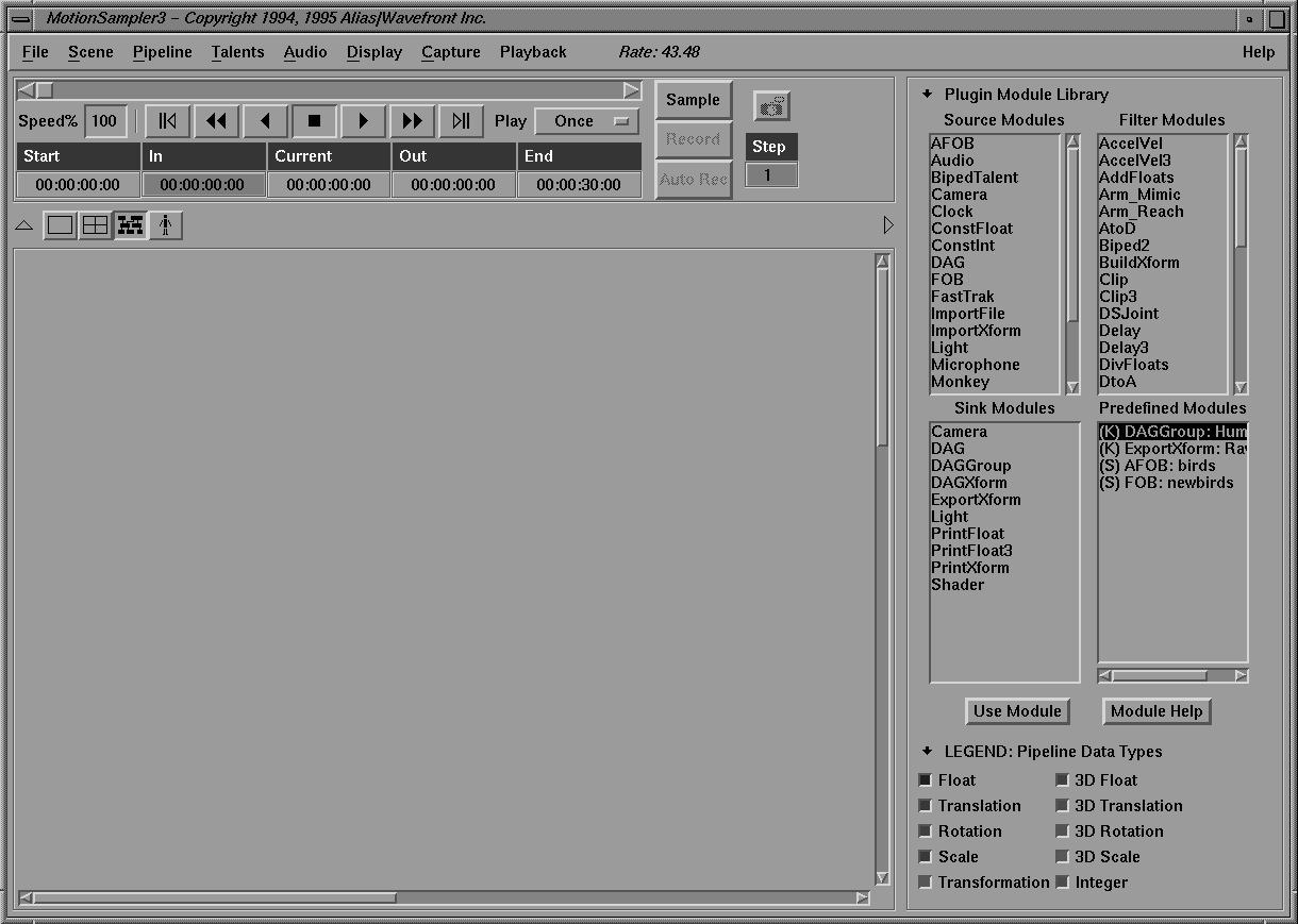
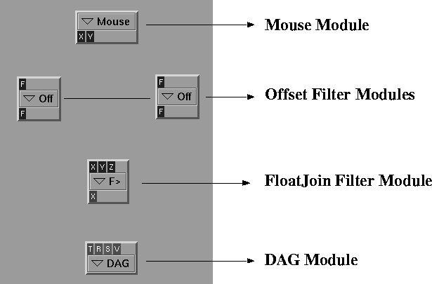
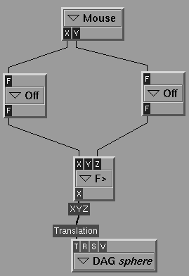
This section of the tutorial shows you how to create a pipeline to control the X and Z position of the sphere with the mouse. A DAG sink, a Mouse source, a FloatJoin (to join three float parameters into a vector) and a couple of Offset modules are needed to scale the mouse coordinates correctly.
The MotionSampler window changes to appear as follows:
A module tile called DAG appears in the upper left corner of the View/Edit area.
| Make sure you select the modules from their correct list. |
As you double-click each module, it is displayed in the View/Edit area. The module tiles pile one on top of the other in the upper left corner of the window so that they appear as follows:
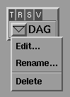
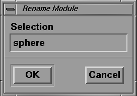
The DAG sink module must have a related wire file. The sink module's name should be matched with the name of a dag node.
To connect the modules to each other and form a pipeline:
Your pipeline should appear as follows:
The next step is to scale the motion coming from the Mouse source to match the wire file more appropriately.
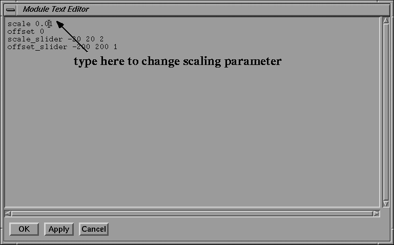
The Mouse source reports actual cursor position, so if you have a 1280x1024 monitor, these positions have a large range. The Offset modules are used to change this scaling.
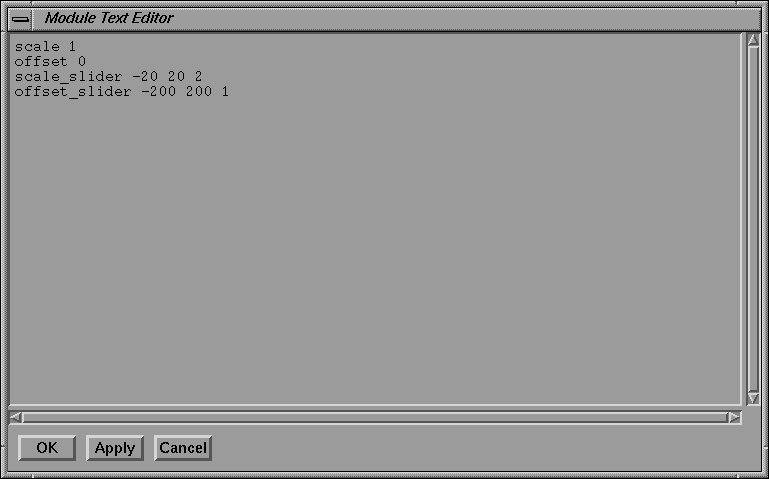
The Module Text Editor appears displaying the Offset's parameters as follows:
|
If you are having trouble generating this pipeline, it has been stored as
Tutorial1.pipe. You can load the stored pipeline by selecting Pipeline Retrieve
Pipeline from the menu bar, and selecting Tutorial1.pipe from the File Browser.
Retrieving the stored pipeline also clears out the pipeline you have been
working on.
|
As you move the mouse and the position of the sphere changes, you may need to zoom your view out to see it.
| Because the mouse is defined as the motion capture device, it is inconvenient to click the Sample button each time you want to enter or leave sampling. |
| The F1 key is the keyboard shortcut to toggle sampling on and off. |
You have now done live motion sampling with MotionSampler. Next, you will record data and see how it can be played back, and how animation can be overlaid with previous work.
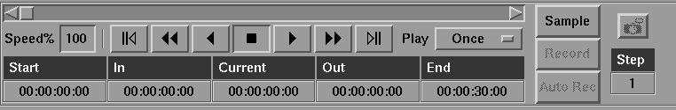
The Shuttle Bank is like a VCR, with controls for forward, reverse, and stop. The knob in the slider above the VCR controls can be dragged.
| As you play forward or reverse, or as you drag the knob, the time displayed in the Current box changes. MotionSampler's current time settings are contained in the Shuttle Bank. |
The animation of the previous movements of the mouse are replayed.
10. Press the following button to stop the playback:
| You can adjust the view with the view controls while playing back the animation. |
11. Select Playback Use Min/Max to set the shuttle's Start and End frames to be the duration of the animation.
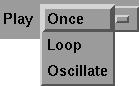
12. Select Oscillate in the Play menu next to the shuttle controls as follows:
Now when you start playback, the animation replays continuously, first forward, then in reverse, and so on.
| You can also select Loop to replay the animation continuously forward. |
You can record additional motion on top of this original animation.
| The sphere motion previously captured moves the sphere at the same time as you are moving the cube. |
11. Exit Record mode by pressing the F2 key and exit Sample mode by pressing the F1 key.
12. Reset the shuttle to frame 0 and play back the result. Both the motion on the cube and sphere play back, with motion recorded separately on each.