The design process is not linear. You spend many hours exploring different concept possibilities, often re-evaluating the direction of a design. To get approval for a design before investing too much time in a particular direction, you often draw fast 2D sketches.
You can use Alias to develop these initial sketches into a more realistic model, but previously, the benefits of visualizing ideas in 3D were not available until later in the design process. However, in this lesson you'll learn how to combine 2D sketches with rapidly built 3D surfaces to create a true 3D sketch to evaluate, develop and present your ideas. The process described is called the Concept Modeling Workflow, and the tools you will use include:
With the Concept Modeling Workflow you work with sketches and models to create the final effect. The resulting models have a rough look similar to the traditional marker sketch, with the added bonus of being able to tumble and view the design from any angle. You can even create simple turntable animations to present the design ideas to your client.
This lesson introduces the Blend Curve toolbox, which lets you place and edit curves with great flexibility. You will create freeform curves without being given exact coordinate positions, drawing the curves with underlying sketches as your guide. The curves you draw do not have to match the illustrations exactly, but it is important that you use the tools and workflow shown in the lesson.
The idea behind the lesson is to give you a feeling for how to work with Blend Curves, Construction Planes, and Curve Networks in the 3D modeling world. Each part of the lesson explains a different way to use the Blend Curve to create lines freely, so do try the entire lesson. You may want to go through the lesson more than once to best understand this new way of working.
You'll design a 3D sketch of a bicycle helmet using the Concept Modeling Workflow. There are three basic steps:
With the Concept Modeling Workflow, you can develop a number of rough design ideas in a short time and speed up the decision process. These steps are described in more detail below.
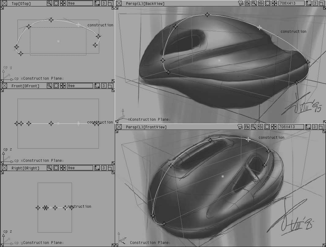
Build a simple primitive model in Alias with key hard points. This lesson uses front and back perspective views and the three orthographic views of the helmet design. In general, you can start with any number of sketches, or even photographs, that you place in perspective or orthographic views.
Lock the front and back perspective views and output them as pix files to import into StudioPaint.
Use the imported Perspective views as underlays to create 2D sketches of the shape from the front and the back. Save these sketches as pix files.
Import the sketches back into Alias as dimmed image planes. Use the sketches to trace the design in 3D.
Set up construction planes that help you trace sketches directly in the perspective windows. Use Blend Curves to create character lines on the construction planes; these curves define the shape of the 3D design and create a network of curves that will be used later to build surfaces.
After the curve network is drawn, use the Curve Network tool to quickly generate a workable surface from the character lines.
Project the 2D sketches onto the model as a surface texture to capture the details. This gives the final rendering the look of a sketch that can be tumbled and viewed in 3D space.
Create a rendering or animation of the 3D model that lets you see the 3D "sketch." You can then evaluate the design and present it to your client.
The first step of the Concept Modeling Workflow is to create 2D sketches. This section explains how to draw two sketches that show the bike helmet from the front and back, and how to align them in two perspective views.
Retrieve a pre-made model of the helmet's hard points to use as a starting point.
Lesson_33.
| Tip: Move tools to the tool shelf for easy access as you work through the lesson. |
CourseWare is your current project directory, so that texture files will be saved in their proper location as you work.
L33_Conceptstart and click the Open button.
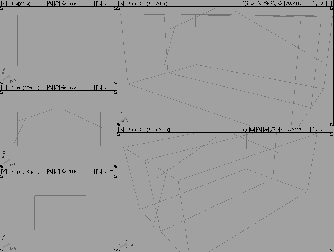
The windows display a templated model of an object bounding box and several hard point lines. There are five views: three orthographic views on the left and two perspective views on the right.
The hard point model defines the basic proportions of the proposed design. Both the outer bounding box of the helmet shape and its center line are drawn. A few single span curves are also included to help define the main center line of the helmet.
The two perspective view windows have an (L) next to the window name, which indicates that the two windows are locked. You cannot use a camera or the view icons in locked windows.
Tip: To lock view windows, choose Edit  Cameras... from the Windows menu and turn Cameras... from the Windows menu and turn Camera Lock to On. |
After the hard point model is built, you need to export the two perspective views as images that can be traced in StudioPaint.
| Note: If you do not have StudioPaint, skip to Importing the sketches as image planes back into Alias on page 635. |
The following steps outline how to export 2D images of the model as pix images.
FrontView perspective window to make it active.
Current window.
Front_trace and click Save Window. This image is now stored in your pix directory.
BackView, using the name Back_trace.
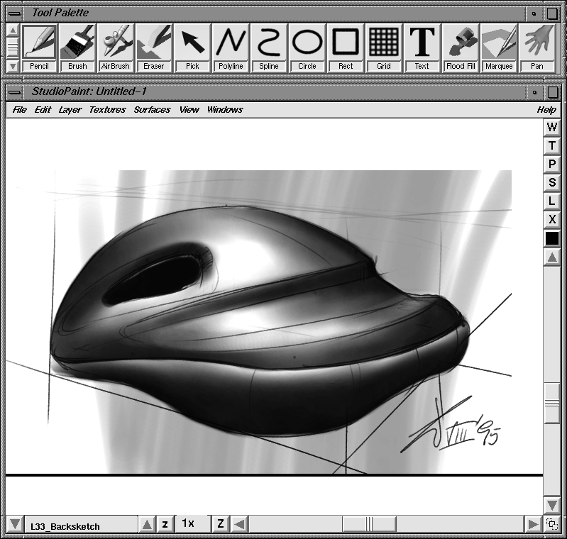
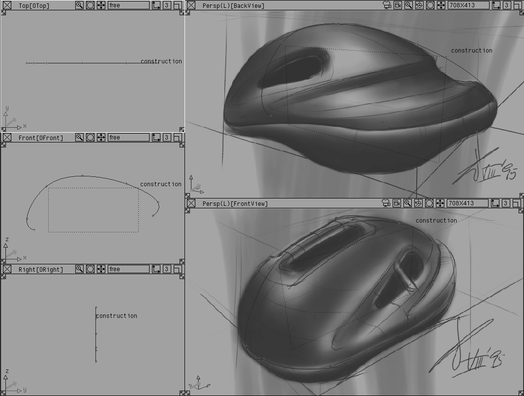
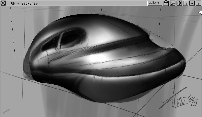
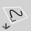
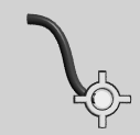
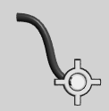
Load the pix files in StudioPaint and trace them. Using the hard points as guides, create two detailed sketches of the proposed design that work together in 3D space. The sketch below is a sample back view sketch after being traced in StudioPaint. It is saved as a pix file.
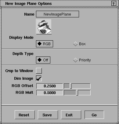
Import the 2D sketches into Alias to help trace character lines in 3D. Import the sketches as image planes using a special dim option that softens their appearance below the wire lines.
FrontView perspective window to make it active.
Image plane - .
.
New Image Plane Options window, turn on the Dim Image option. Set the RGB offset to 0.25 and the RGB Mult to 0.5.
This adjusts the brightness and contrast of the image, which makes it easier to work with the wire lines as you trace the images.
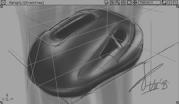
L33_Frontsketch, located in the pix directory. A dimmed version of the helmet sketch displays in the FrontView window.
L33_Backsketch into the BackView perspective window.
Each sketch should sit more or less within its bounding box. You'll use these 2D sketches to define the shape of the 3D sketch.
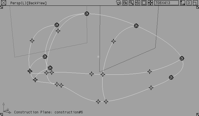
After you've created 2D sketches, and aligned them in the perspective windows, you can use them to trace the shape of your 3D sketch. To do this, you will create several character curves:
You will use the Blend Curve toolbox, combined with construction planes that you create to draw the traced curves in the perspective windows. The basic order of working is to:
Each of these steps is explained in more detail below, as you create the different character curves.
Construction planes are flat surfaces on which you can draw planar curves. Use them to draw in the Perspective view windows without relying on snapping functions.
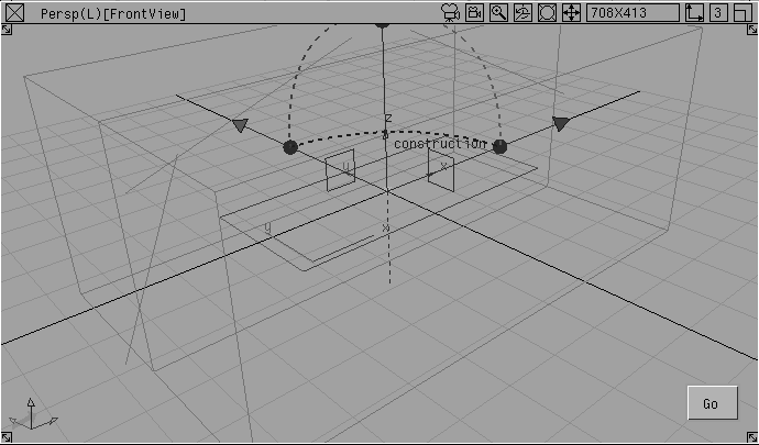
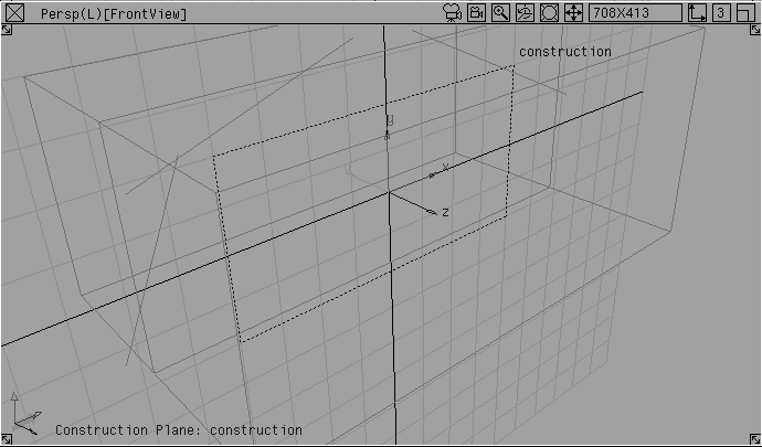
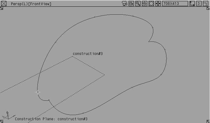
The first character curve to draw is the center line of the helmet. This section explains how to place a construction plane at the origin that is aligned with the X and Z axes so that you can draw the center line from the Perspective view.
Image planes. This turns off the image planes while you place the construction plane.
Grid. This turns on the working grid, which helps you to set the construction plane.
 Select Grids Free Plane from the palette.
0 to place the construction plane at the origin.
A manipulator icon for the construction plane displays in the perspective views; use the icon and/or its manipulator handles to orient the plane.
| Note: Manipulator handles on planes and primitives are a new feature in Alias. Manipulator handles are only shown on the plane pictured above. They are understood but not shown on all other planes pictured in this chapter. For more information on manipulator handles, see What's New in Alias. |
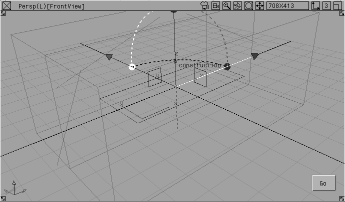
FrontView window, click the dashed red arc to make it active. This allows you to re-orient the plane by rotating around X.
90 and press Enter to rotate by 90 degrees around the X-axis. The construction plane is now aligned with the world space XZ plane.
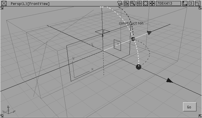
The new plane is now the drawing surface, and the manipulator is removed. The reoriented working grid shows where you will be drawing.
As the construction plane is set, the three orthographic views flip so that they now reflect the true length views of the construction plane's axes. For example, the Top view looks down the Z-axis of the construction plane, which now appears like a side view of the helmet.
|
Note: If the orthographic views do not flip to reflect the construction plane axes, then select Grids Set const plane from the palette, and pick the construction plane. |
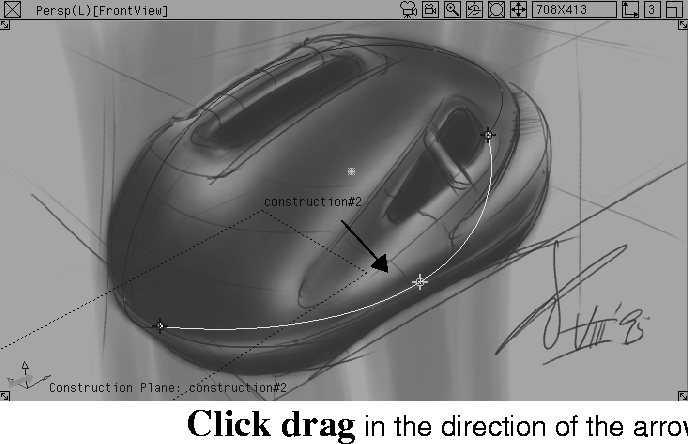
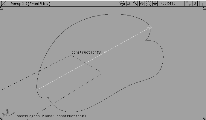
After you've placed the construction plane at the origin that is aligned with the X and Z axes, use the Blend Curve tool to draw the center character line from the perspective view.
You will draw in the vertical working plane that runs down the middle of the helmet, with the construction plane active. It is similar to positioning a vertical chalkboard in the center of your future 3D helmet.
Image planes. This displays the 2D sketches with which to trace the character lines.
Grid. This turns the working grid off, so you can see the sketches more clearly.
Use both the front and back sketches to align the character curves. One of the most tricky things about tracing two perspective sketches is to place the curve points so that they work in both views. If the dimensions are exaggerated in one sketch, you will have a hard time placing a curve point that fits both views. In this case, make a design decision and place the point where it seems best suited. Use the orthographic views to help decide what works.
This is just a rough cut at the center line. You will edit the character curve later.
 Select Curves Blend curve toolbox from the palette. The Blend Curve tools display in a floating palette. You can use these tools from here or drag them to a shelf.
 In the toolbox, select BlendCrv Tools Blend curve create-.
Curve Degree to 3.
Use a Curve Degree of 3 for the example in this lesson. If you have higher degree curves available, you can use them in your own work to create better quality curves and surfaces.
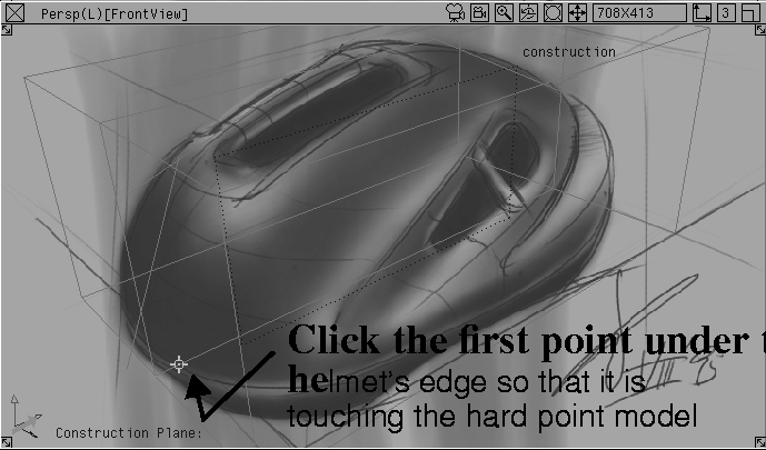
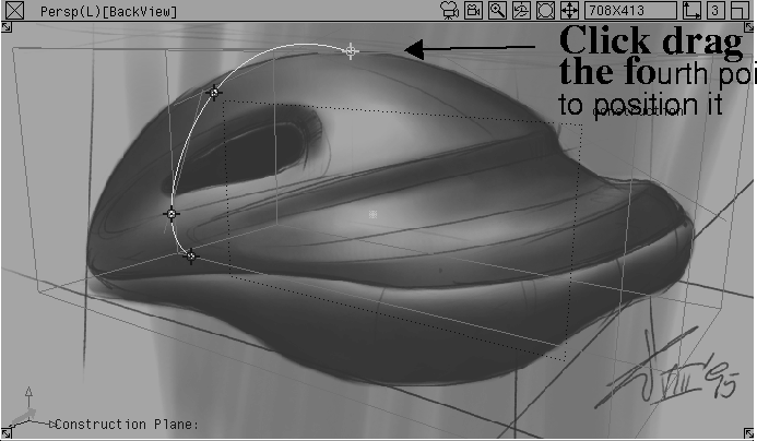
FrontView perspective window, click just under the edge of the helmet in the sketch to place the first point. Since this edge is hidden in the view, use the hard point bounding box to help you.
Note that with the construction plane active, you don't need to turn on a snapping function; you can draw on the plane as if it were a 3D drawing surface.
BackView perspective to see if the placement of the curve point is accurate in both sketches. Drag up or down to match the placement.
Since the sketches are different, the dimensions may not match exactly. Use the orthographic views and your own judgment to place the curve point. When the point is appropriately matched in both sketches, release the mouse button.
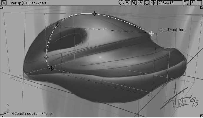
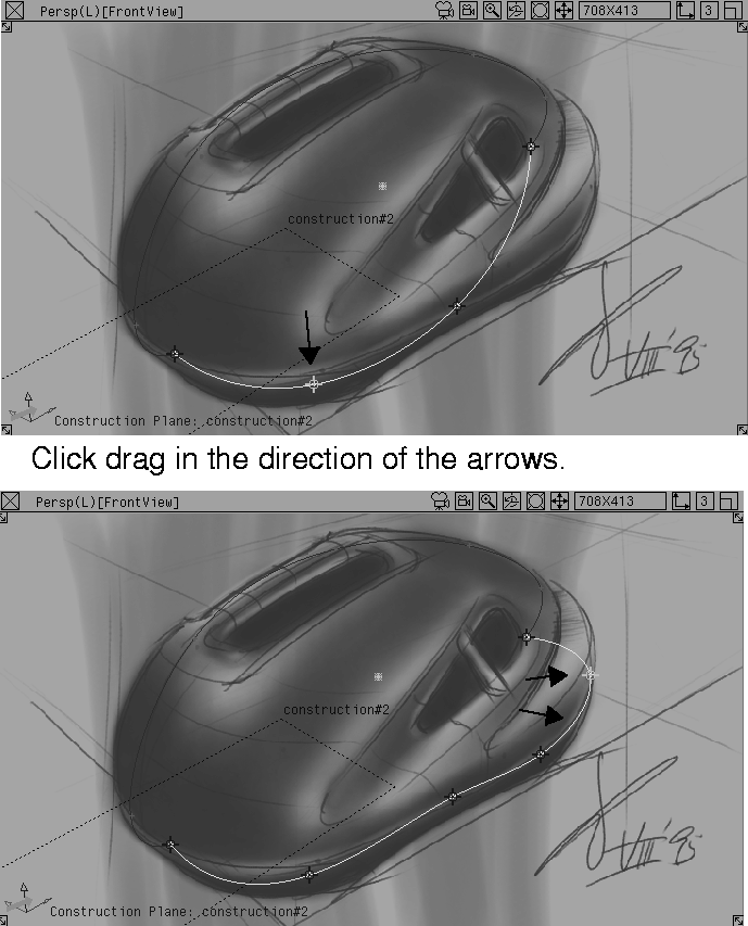
The FrontView perspective doesn't clearly show good points to snap the center line curve to. Finish the tracing on the second sketch in the BackView.
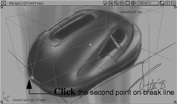
BackView, click about half-way down the length of the helmet to place the next point.
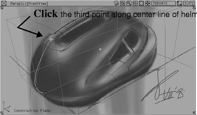
BackView, place the next point where the center line touches the helmet's break line between the gray and blue parts of the sketch.
| Tip: Because this point creates a curl at the end of the curve, it may not match perfectly. You'll usually need to edit the points of the Blend Curve to refine its form. |
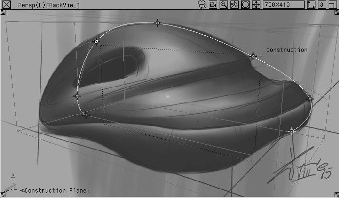
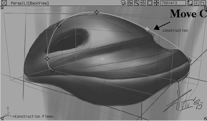
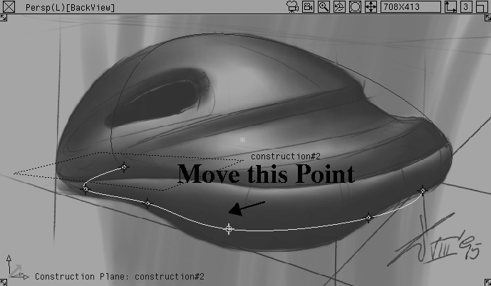
To edit a Blend Curve, simply pick a constraint point, and move it; the curve updates in a fluid manner. You can also add more constraint points. In this section, you will trace the shape of the character line point by point.
 Select BlendCrv Tools Blend curve edit.
| Note: It is not possible to pick and edit Blend Curve points in one smooth motion. You must first pick the point, release the mouse button, then click-drag. |
FrontView and the BackView. Refer to both perspective windows as you edit.
You only needed the hard point model to create the sketches and align them in the perspective views. To draw the other character lines, you will trace the sketches themselves so you can hide the hard points.
You do not have to hide the construction planes while you work. When they are inactive, they display lightly so as not to interfere with your work.
However, hiding the guides that you don't need will remove clutter from the modeling views, so you can work on one plane at a time.
 Select Pick Nothing; then select Pick Template. Click-drag a pick box around the entire hard point model.
 Select Grids Tgl const plane. This makes the hidden ground grid active and dims the construction plane. The orthographic views return to their regular orientation.
 Select Pick Object. Click the construction plane to make it active.
You can retrieve the construction plane later if you need it.
Helmet_curves and click Save.
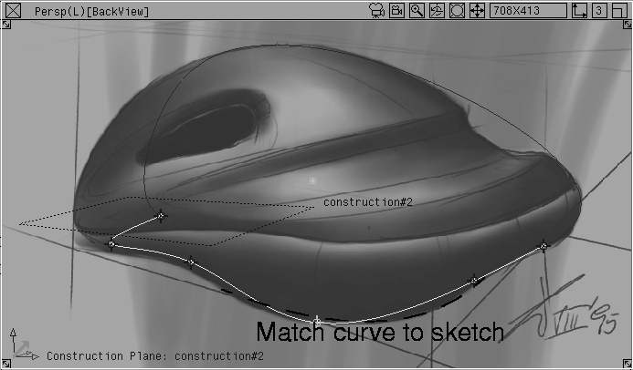
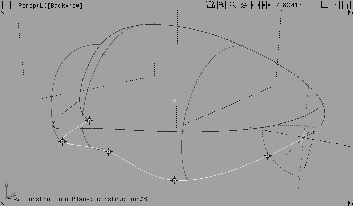
Now that you have drawn the centre line character curve, you will use the same process to create the next curve: the bottom edge of the helmet.
This character line runs between the two ends of the center line. Since the helmet is symmetrical, you can draw the character lines on half of the design and then mirror it to create the final shape. To insure tangency will be maintained with the mirrored half, you must place the bottom edge line so that its ends meet the center line (the mirror line) perpendicularly. This is easy when you use construction planes.
In the sketch, you can see that this bottom edge is a 3D curve; that is, it "bulges" out along the Z-axis. Draw this curve in the 2D space of a construction plane and then edit the CVs so the curve works in 3D, using the perspective and orthographic views as guides. Because the Blend Curve tool is used differently, this is discussed in a separate section.
When you first draw the curve, it probably won't match the sketch at all. You will match the curve when you edit it. Matching the curve in "free" 3D space is explained in more detail below.
Recall that the basic order of the work is:
Free Plane tool.
Blend Curve tool, using the 2D sketch as a guide.
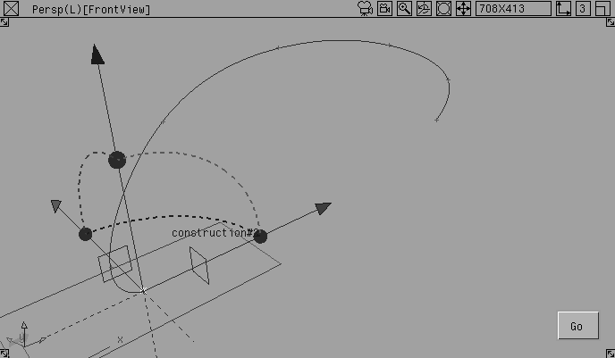
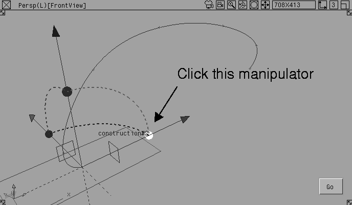
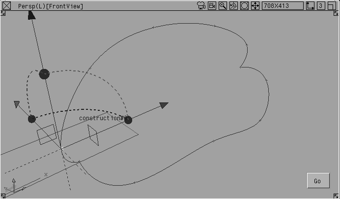
You will add a construction plane that runs on the Y-axis along the center line.
Image planes. It's easier to place the construction plane when the images are hidden.
 Select Grids Free Plane.
Ctrl key to temporarily turn on magnet snapping and click the first constraint point of the center curve.
This places the plane's manipulator at this point. The manipulator has several handles that help you position the plane.
Ctrl key and click the last constraint point at the other end of the center curve.
The line that runs between the two points defines the plane's X axis, thereby defining the orientation of the new construction plane.
The construction plane runs between the two end points of the center curve. It has its own working grid in relation to the construction plane icon. If you want to see this grid then you can toggle it.
Note: The orthographic views change to display the true length views of the construction plane axes. The Top view looks down at the helmet along the Z-axis of the new plane. Dolly and track in these windows to the view shown above to see the profile curves properly. |
To create this character line, you will use the Blend Curve tool slightly differently. For the center line, you traced the curve point by point. For this line, you will lock the ends first, and then add more points along the curve to define its shape.
Use the two endpoints of the center line to lock the ends of the bottom edge.
 In the toolbox, select BlendCrv Toolbox Blend curve create.
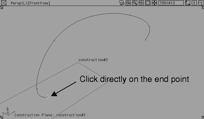
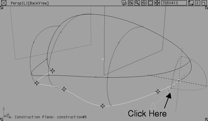
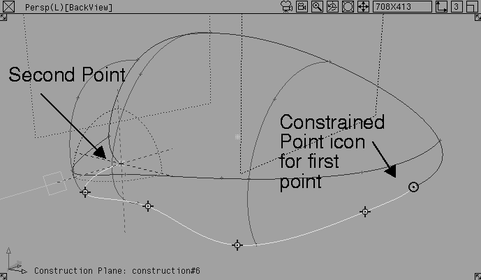
Ctrl key and click directly on the left endpoint of the first center curve. This places a constraint point for the bottom edge, and locks the point to the first curve.
| Note: With other drawing tools, you click near the snapping point, but you must click directly on the snapping point of Blend Curves to lock the curves. |
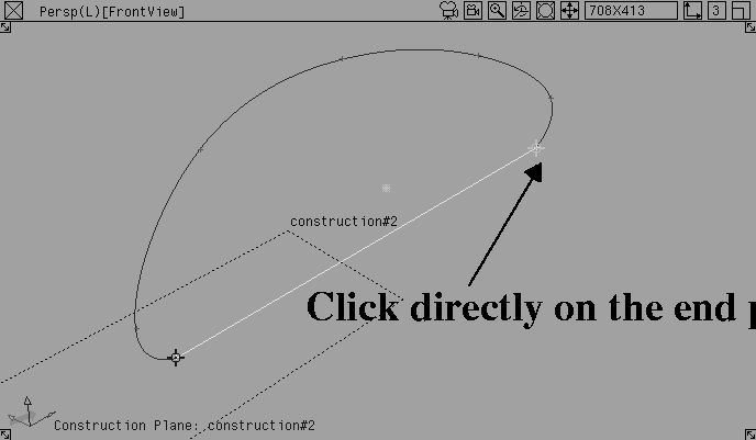
Control key and click directly on the right endpoint of the first curve. Now you have a single span running between these two snapping points.
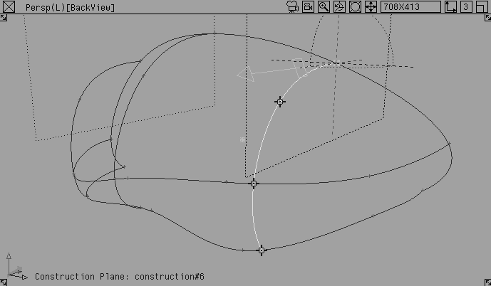
Turn on the image planes to reveal the sketches, and add more constraint points, using the sketches to follow the curve of the edge.
The Blend Curve tool provides an intuitive way to create a curve using constraint points to add complexity to the curve.
Image planes. Use these to trace the character lines.
FrontView perspective window and drag out to the edge of the helmet.
Because the construction plane is active, you are dragging along this defined working grid.
The bottom edge curve now sits on the construction plane, but does not exactly match the sketches in either of the two perspective views. To match these, you need to manipulate the curves in all three dimensions, without the constraint of the construction plane.
Working in 3D or free space is tricky, because edits made in one view may not look correct in another view. As a 3D designer, your goal is to draw a curve that looks good from all points of view. As a result, the following steps are very important.
If you can't get an exact fit between the curves and the sketches, don't worry. Sketches drawn from two points of view are rarely perfect matches and you must often make creative decisions as you go. Try to refer to all of the modeling views to help you place the points.
 In the Blend Curve toolbox, select BlendCrv Tools Blend curve edit.
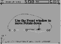
Front view with the right mouse button to drag the point down.You are now manipulating the curve in 3D or free space.
Use all the windows to check whether or not the curve is aligning with the sketch; an edit that looks good in one view may not look good in another.
Blend curve edit still selected, continue to edit all the constraint points that seem out of place until you feel that you have matched the shape of the curve in both sketches.
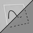
The curve shown in the above illustration is one possible solution that matches the FrontView sketch better than the BackView sketch. As you work through a concept, you must decide which sketch best suits your design intention, because it is unlikely that the two sketches will be perfect matches. If you decide that you like the form in the BackView sketch the best, your curve may look a little different.
 Select Grids Tgl constr plane. This makes the ground grid active and dims the construction plane.
Nothing, then select Pick Object. Pick the second construction plane.
Select Grids Tgl constr plane. This makes the ground grid active and dims the construction plane.
Nothing, then select Pick Object. Pick the second construction plane.
 From the ObjectDisplay menu, choose Invisible. This lets you retrieve the construction plane later, if you need it.
Save.
From the ObjectDisplay menu, choose Invisible. This lets you retrieve the construction plane later, if you need it.
Save.
The next character line defines the outer edge of the helmet that separates the lower gray part from the upper blue section.
Draw this lateral character line the same way as you did the bottom edge.
Image planes.
 Select Grids Free Plane.
Ctrl key to temporarily turn on magnet snapping, and click on the second constraint point of the center curve (counting from the left end).
This places the plane's manipulator at this point. The manipulator has several handles that help you position the plane.
Ctrl key and pick the second-to-last constraint point at the other end of the center curve.
The line that runs between the two points defines the plane's X axis, thereby defining the orientation of the new construction plane.
 In the
 Blend Curve toolbox, select BlendCrv Tools Blend curve create.
Ctrl key and click directly on the second point of the centre curve (counting from the left). This places a constraint point and locks it to the center line.
Ctrl key and click directly on the second-to-last point of the center line. Now you have a single span running between these two snapping points.
Image planes to display the sketches to trace more character lines.
 In the Blend Curve toolbox, select BlendCrv Tools Blend curve edit
 Select Grids Tgl const plane to make the ground grid active and dim the construction plane.
 Select Pick Nothing, then select Pick Object. Pick the third construction plane.
Save.
Select Pick Nothing, then select Pick Object. Pick the third construction plane.
Save.
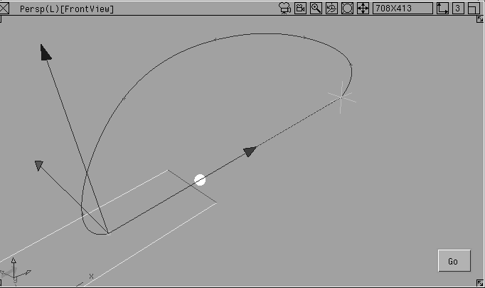
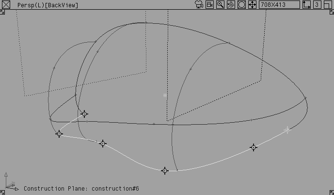
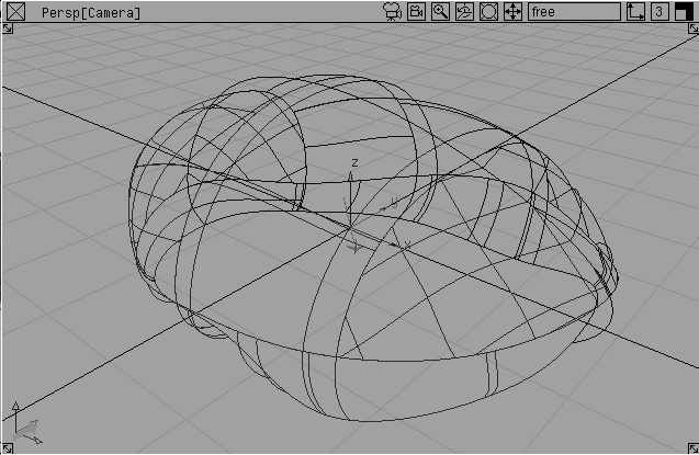
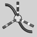
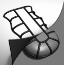
After you have defined the lateral lines, you need to place some cross lines to create the final network of curves; you need both longitudinal and lateral curves. These curves must intersect with the other curves in the network so that you can use the Curve Network tool.
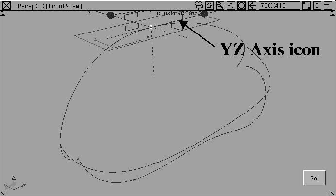
You will need to construct a YZ construction plane.
Image planes. You won't need the sketches to add the lateral lines.
 Select Grids Free Plane.
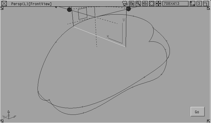
Ctrl key to temporarily turn on point snapping and click directly on the control point at the center of the center line.
The construction plane manipulator displays.
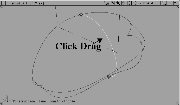
When a construction plane is on, a curve snaps to the intersection of the construction plane and any curves that intersect it. This is very useful for drawing a new curve that intersects multiple curves and remains in a planar condition. Use this feature to create the cross lines.
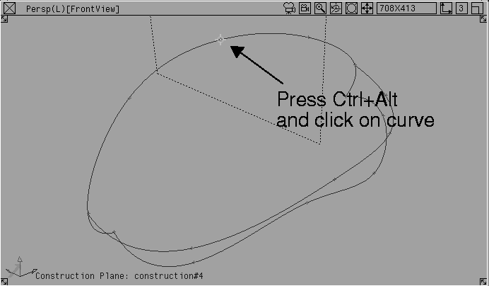
 In the Blend Curve toolbox, select BlendCrv Tools Blend curve create.
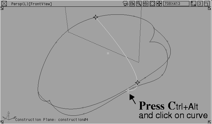
Ctrl+Alt and pick the center line.
Curve snapping locks the first point to the intersection of the construction plane and the center line curve. Release the mouse button at this intersection point.
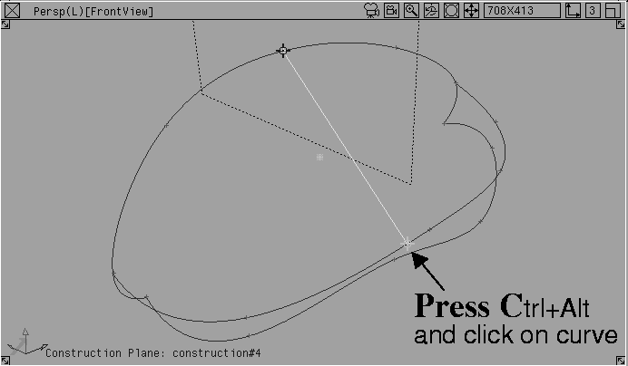
Ctrl+Alt and pick the next lateral line. This locks the second point to the intersection of the construction plane and the chosen curve.
Ctrl+Alt pick the bottom edge line. This locks the third point to the intersection of the construction plane and the bottom edge.
The Blend Curve now spans the three lateral curves, the centre line, the middle line, and the bottom edge.
 Select Grids Tgl constr plane. This makes the ground grid active and dims the construction plane.
 Select Pick Object. Click on the fourth construction plane with the middle mouse button.
Save.
Select Pick Object. Click on the fourth construction plane with the middle mouse button.
Save.
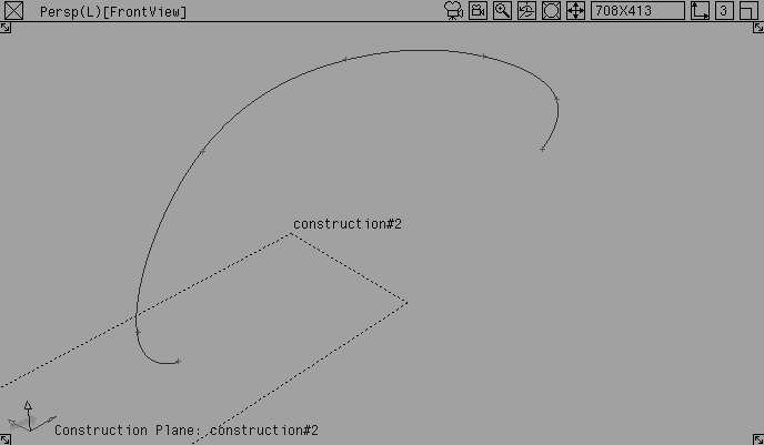
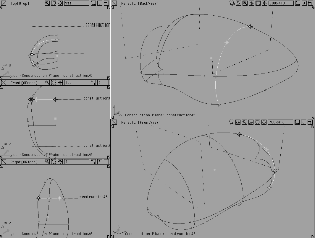
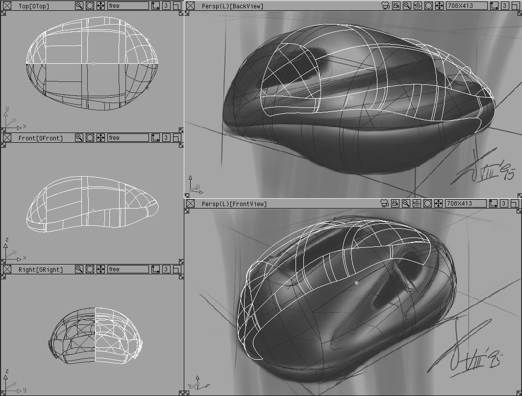
Create two more cross lines at the front and back of the helmet. Use construction planes and the Ctrl+Alt keys to find the intersections of the planes and the curves. The curves should appear as follows:
All of the character lines you have drawn, except for the center line, will be mirrored to create the other half of the helmet.
In order for the final helmet to be smooth, all the curves must meet the center line with their ends tangent to the mirror axis - that is, perpendicular to the center line. This will ensure that the two halves of the helmet will meet properly.
 With nothing picked, from the Blend Curve toolbox, select BlendCrv Tools Blend curve edit.
 From the Blend Curve toolbox, select BlendCrv Tools Constraint Interpolation Direction Blend constraint interp direction.
A manipulator appears. It controls the orientation of this control point. A series of dotted lines indicate the XYZ axes.
The constraint point now has a different icon to show that its orientation has been constrained.
 From the Blend Curve toolbox, select BlendCrv Tools Blend curve edit.
 From the Blend Curve toolbox, select BlendCrv Tools Constraint Interpolation Direction Blend constraint interp direction and reorient the point perpendicular to the center line axis.
 From the Blend Curve toolbox, select BlendCrv Tools Blend curve edit.
Shift key and use the middle mouse button to click drag a pick box over one of the other curves. It is now active.
 From the Blend Curve toolbox, select BlendCrv Tools Constraint Interpolation Direction Blend constraint interp direction and reorient the endpoint perpendicular to the center line axis.
 From the Blend Curve toolbox, select BlendCrv Tools Blend curve edit.
Shift key and use the middle mouse button to click drag a pick box around all the curves. All the endpoints with edited orientation should have a highlight icon.
Save.
Because Blend Curves lock constraint points from different curves together, the character lines are an integrated set of curves. If one of the original curves is edited, the intersecting curves will follow. In turn, you can only move the intersecting curves in line with the original curve.
Note: If you move a constraint point and it is not updating properly, it is not intersecting. To correct this, click-drag the constraint point directly over the other curve and then choose Yes when asked if you want to join the curves. |
Read more about Blend Curves in NURBS Modeling in Alias. Use them for quick models such as this helmet, or for more complex character lines needed for finished models.
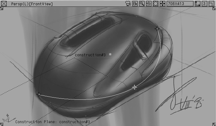
After you use the imported 2D sketches to build a surface skeleton for the final 3D sketch, you can create the 3D model.
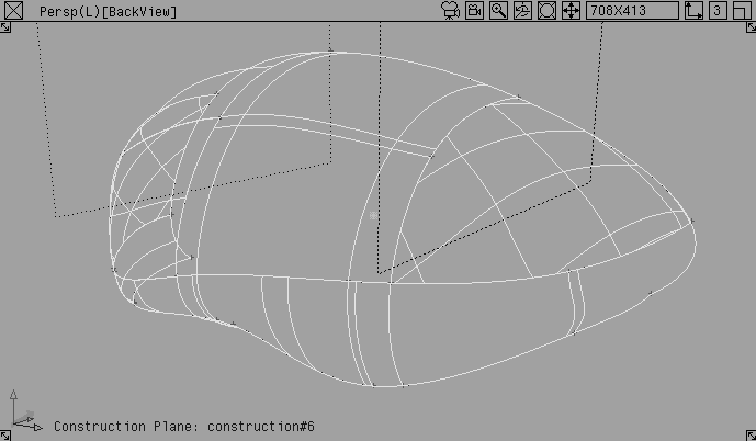
Now that you have defined the network of curves, use the Curve Networks tool to create a patchwork of surfaces on the framework to define the surface of the helmet.
Because you want to duplicate one half of the curve network along a mirror axis, you will create a curve network with tangency, and then identify the implied tangency at the center line.
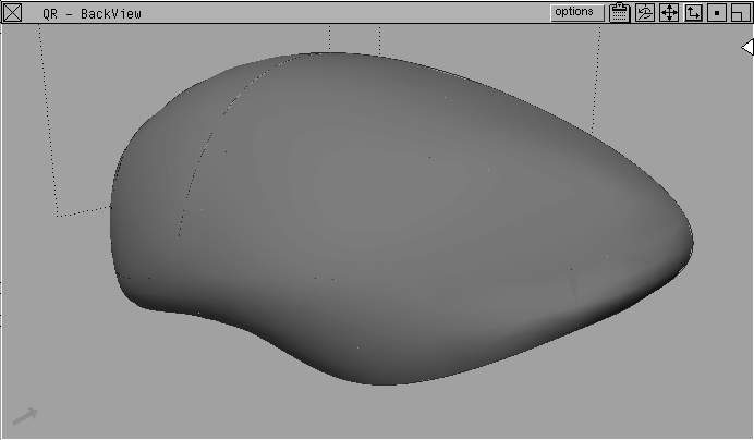
Then you will Quick Render the surfaces to check that the half of the helmet surface is correct.
 Select Surfaces Curve networks... This reveals a separate toolbox with the Curve Networks tools.
 With nothing picked, select CrvNet Tools New network. Click-drag a pick box around all of the curves.
 Select CrvNet Tools Implied tangency. Pick the center line to create a condition of
 Implied tangency across the Y-axis.
This tool simulates tangency when the opposing surfaces don't yet exist. After you mirror the surfaces, you'll have better tangency between the two halves.
Curve Networks toolbox.
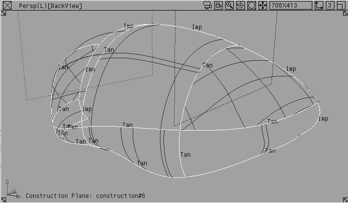
 With nothing picked, select Pick Object. Pick all surfaces.
BackView window to make it active.
.
Output Image option to Off and click Go.You can now see the surfaces rendered with the default blue shader.
If the edges of the surfaces that make up the network are faceted instead of smooth, increase the Render Subdivisions to make it render more smoothly.
 Click in the
 QuickRender window to close it.
Object. Click-drag a pick box around the curve network.
Render stats...
Shift key and select all the surfaces.
Minimum subdiv to 8 and the Maximum subdiv to 12 for each surface.
If you want to get rid of all the seams, you can further raise the Render Subdivision settings.
| Tip: Remember that higher subdivision settings take longer to render. If a seam is acceptable at this "sketching" stage, don't set the subdivisions too high. |
Now that half of the helmet has been modeled, apply the two sketches as a texture map to the new model. This creates a true 3D sketch that lets you evaluate your concept and present it to your client at a very early design stage.
To do this, create a projection shader, and then convert the solid texture into a series of parametric maps to project on the model.
The helmet shader uses solid projection techniques to projects the FrontView and BackView image planes onto the surface.
Image planes. You will use the images to generate the helmet shaders.
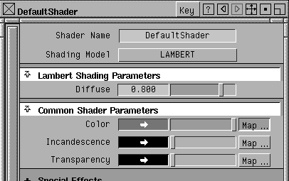
Shaders... The Multi-lister displays the default shader.
Default shader to open the shader editor.
Shader editor window, click the Map button next to Color.
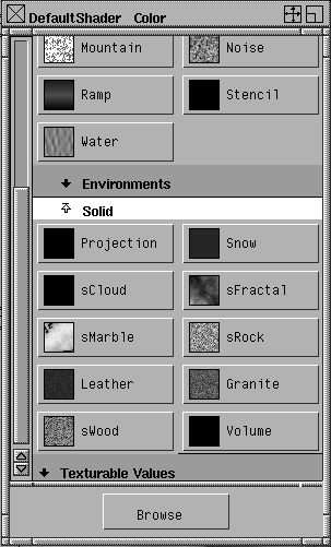
Texture Window, scroll to the Solid section and open it.
Projection option as the texture type.
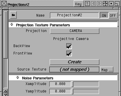
The Shader editor is now the Texture editor.
Camera from the Projection pop-up.
FrontView and BackView options
Create.
You have now created texture projections using the two image planes. They are projected back onto the 3D model.
The shader for this exercise was built using several pieces. The two image planes are now mapped as stencils that use transparency maps so you can focus on part of the first sketch for the front projection and part of the second sketch for the back projection. This ensures that the two sketches don't conflict with each other.
Transparency maps are centered by default, but you must move the maps of the sketches to get the correct projection.
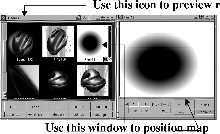
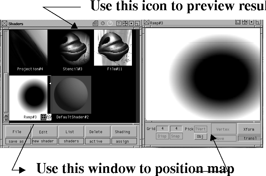
Projection#2 shader to display shaders Stencil#2 and Projection#4.
Stencil#2 to open the icons for the corresponding File and Ramp.
Projection#4 shader. Below are all the expanded shaders shown as small shader icons.
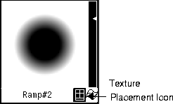
Texture placement icon in the bottom right corner of the Ramp shader to adjust the first transparency map.
A window appears that lets you move and scale this map so the Stencil texture that combines the image plane and the transparency map are better aligned.
Stencil texture is focused on the Front section of the sketch.
BackView window to make it active.
.
Quality to High and the Shading Frequency to 10.
You can now see the two sketches projected back onto the model.
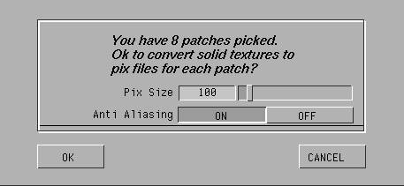
After you create the projection shader, with the map properly aligned, you must convert the solid texture into a series of parametric maps that map onto each of the helmet surfaces. This lets you mirror the surfaces of the helmet and have the textures mirror at the same time. You cannot mirror solid textures in this way.
DefaultShader in the Multi-lister.
Pix Size to 100 and click OK.
This converts the projection textures into parametric maps that fit perfectly onto the 8 surfaces of the helmet.
The resulting shader is a special shader type that contains references to all eight of these textures. These textures are placed in a special directory in your current pix directory.
Final_Helmet in the file lister and click on Save wire.
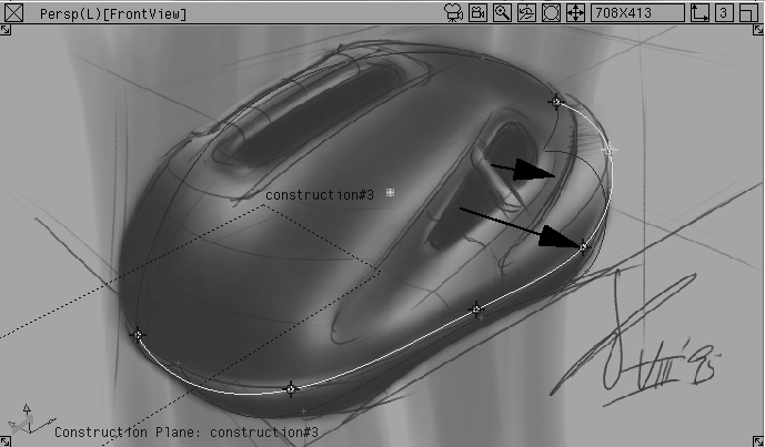
With the model now ready, you can mirror the surfaces of the helmet and view it from other perspective angles. This will help you evaluate the design while giving you a 3D sketch to present to your client.
Component -. Turn all options Off except for Curves.
Tgl const plane to return to the default world space.
 Select Pick Object. Pick the helmet surfaces.
.
Select Pick Object. Pick the helmet surfaces.
.
Y scale factor to -1.0 and click Go. The surfaces are now mirrored about the Y-axis.
Since the FrontView and BackView windows are locked, create a new perspective view of the helmet.
. Select the Perspective window type option and click Go.
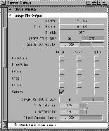
Image File Output section and open it.
Frontview and Backview cameras, to render only with the new camera. Make sure that the Render resolution is set to NTSC, and close the Globals window.
. Select Raycaster as the Renderer Type and turn on the Test Render option. Set the Test Resolution to 0.75 and click Go.
Render status. After the rendering has started, select Show render from the Render menu.
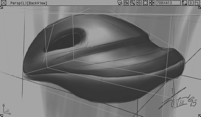
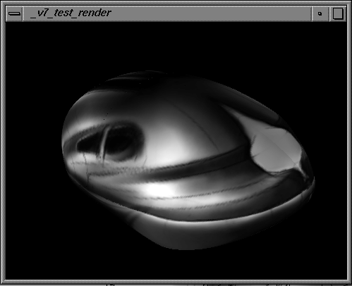
The result is a rendering of the helmet from an angle that is different than the original two sketches. This image can be used to evaluate this design concept and to compare it to other ideas.
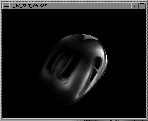
| Note: At the top of the new rendering you can see the orange area where the background of the sketch has been mapped onto the surface. When textures are mapped back onto surfaces, sometimes the background creeps in. You'd need to export the model to StudioPaint 3D to fix the maps and remove the background color. Below is a rendering of the front of the helmet without the background. |
In this lesson you produced a rendering of a 3D design concept sketch. Other ways to preview your work include: