Inverse Kinematics involves the use of special skeleton hierarchies made up of joints. To create a character that uses the skeleton as its deformation frame, you must learn how to set up and animate skeleton joints. When learning to work with skeletons, remember that joint hierarchy can work in the opposite direction of a normal hierarchy. In other words, information can be passed from lower nodes to upper nodes until a root joint is reached.
IK skeletons let you control the movement of characters easily, as well as rotations of the limbs of those characters. They also form the underlying structure that later controls the skin deformation of the characters.
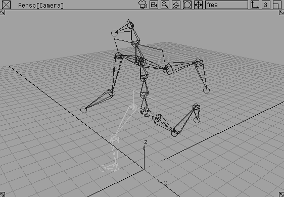
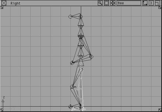
In this lesson, you construct a basic biped skeleton. You also learn to apply IK handles and set some joint limits. You then apply keyframes to animate the movement of the skeleton and its limbs.
For this example, you start with an empty workspace.
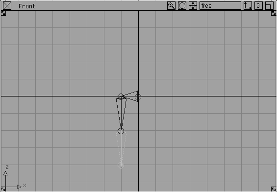
To start, you build a biped-like skeleton using efficient construction techniques and shortcuts available to you in Alias.
 Select Objects
  Draw Skeleton.
Grid button in the upper right of the menu bar to toggle Grid snapping on.
| Note: Since the model is facing us, our left is the skeleton's right. |
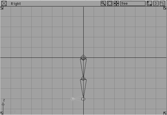
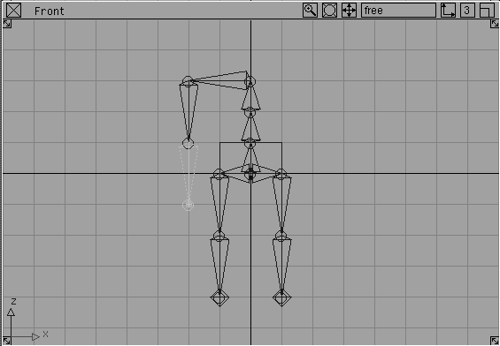
At this point, you have constructed most of one leg. The next step is to construct the foot of the skeleton. To do this, you place the next skeleton joint in the Right window.
 Select Pick Object. Click-drag over or click on a joint of the constructed skeleton.
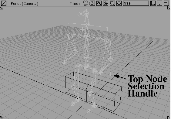
By using Pick Object, you have now selected the top dag node (it would be shown in the SBD window) of the skeleton (the anchor node), which is the hip joint. Draw Skeleton draws joints from the currently active dag node, which lets you draw off the hip to construct the left leg.
 Select Objects Draw Skeleton. In the Front window, click one grid unit to the right of the waist joint to place the left hip of the skeleton.
Shift key and select the UP arrow on the keyboard four times.
Note: Each time you select the UP arrow, you move up one joint in the skeleton's hierarchy, allowing you to traverse the skeleton quickly. To move down a skeleton joint level, use the DOWN arrow. To select a joint at the same hierarchy level as the currently selected joint, such as is the case with the hip joints, select the LEFT and RIGHT arrows. These keys work for any dag node hierarchy. |
|
Tip: If you get lost, select Pick Nothing then Pick Joint. Click the top node of the skeleton to pick it. Both of the legs are highlighted. Again, remember that you must click-drag over or directly on a joint. |
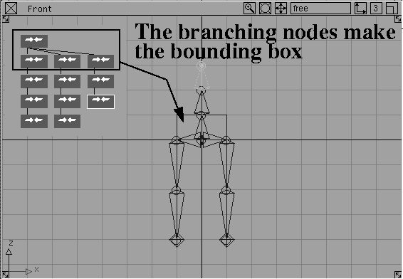
When you placed the first backbone joint, a bounding box appeared around the three joints that branch off from the top node of the hierarchy. This box helps to remind you that the bones leading to these joints all share the same rotational values.
Shift-UP arrow shortcut, press the UP arrow three times to move back up the skeleton's dag structure until the top of the backbone is highlighted with dotted lines. Dotted lines indicate that the selected joint is the parent joint to all the other selected joints.
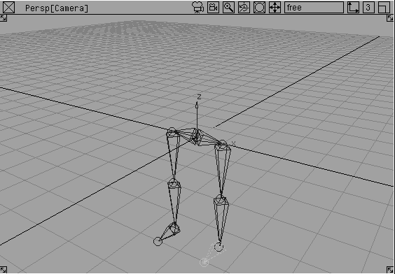
Shift-UP arrow shortcut to go up the character's skeleton until you reach the top of the backbone. The top joint and the two arms should be highlighted.
There are different ways to modify the skeleton. This kind of adjustment is often necessary to reposition the joints to match existing geometry better, or to change the overall proportions of the skeleton.
Grid button to turn Grid snap off.
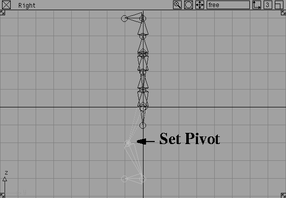
 Select Pick Nothing, then select Pick Joint. With the middle mouse button, click-drag in the Front window over the two knee joints to pick them without picking any other joints.
Local Set pivot. Click-drag with the middle mouse button in the Right window to move the knee joints' pivot positions forward.
Select Pick Nothing, then select Pick Joint. With the middle mouse button, click-drag in the Front window over the two knee joints to pick them without picking any other joints.
Local Set pivot. Click-drag with the middle mouse button in the Right window to move the knee joints' pivot positions forward.
| Note: When moving a joint with the Set pivot tool, you are only moving the joint and not any other part of the skeleton. |
| Tip: In order to prepare the legs for IK, it is important that they already be a little "cocked." The rest position of the legs, then, gives the IK solver information that will help it analyze and interpret IK motion. Had you left the legs straight, the IK solver would not know which direction to begin rotating. |
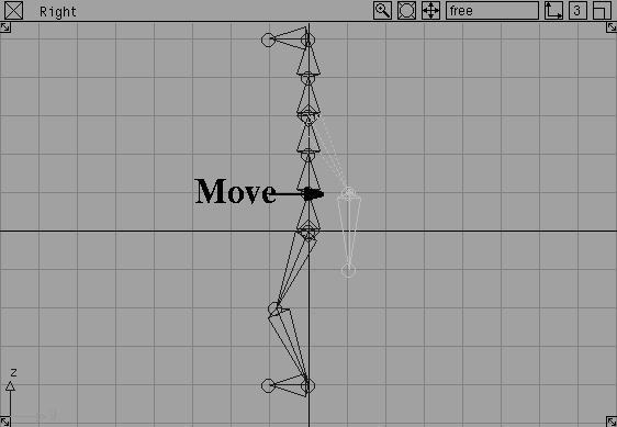
 Select Pick Nothing, then select Pick Joint. Pick the two elbow joints.
 Select Xform Move. Using the middle mouse button, click-drag in the Right window to move the elbow joints back a little.
| Note: When using the Move tool on a joint, all the joint nodes below the elbow joint are also moved. This is a quick way to re-adjust the positioning of a whole skeleton chain, such as an arm or a leg chain. |
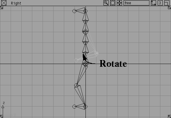
 Select Xform Rotate. Click-drag with the left mouse button in any window to rotate the forearms up to around hip level.
Again, you have put a slight angle in the elbow joint to assist the IK solver. Now the character seems almost poised for action, which is better for the upcoming steps.
| Note: When using the Rotate tool on a joint, all the joint nodes below that joint are also moved. This is a quick way to re-adjust the positioning of a whole skeleton chain, such as an arm or a leg chain. |
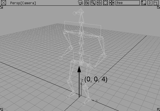
 Select Pick Nothing and Pick Object. Click on any of the skeleton's joints to pick the whole hierarchy.
 Select Xform Move. Press the
 Alt key to temporarily turn on grid snapping and click-drag up so that the character is standing with his feet on the ground plane. The top node will be at (0, 0, 4).
In the last few steps, you have prepared the skeleton joints for the IK solver. To preserve this pose in case you want to return to it during an animation, you must set a rest pose. By default, a rest pose is created when you first place down joints. However, after moving and rotating the joints into new positions, you must set a new rest pose.
The IK solver uses the rest pose as the reference pose for its solution. As a result, different rest poses act differently.
Set rest pose. Now this position will be used by the IK solver.
 Now, select Pick Nothing, then Pick Joint. Click on one of the skeleton joints to pick it for editing.
 Select Xform Rotate. Click-drag with the right mouse button to rotate the chosen joint.
| Tip: One method of animating a skeleton is to Rotate joints like this, then use Set keyframes on the joint rotations. While this solution can be tedious on its own, it is a useful method of applying secondary animation to a skeleton that also uses IK chains. |
 Select Pick Object. Click on any of the skeleton's joints with the middle mouse button to pick it.
Assume rest pose. The character goes back to the rest pose that was set earlier.
Select Pick Object. Click on any of the skeleton's joints with the middle mouse button to pick it.
Assume rest pose. The character goes back to the rest pose that was set earlier.
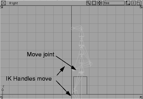
While rotating joints enables you to create a pose for a character, the steps involved often lead to a robot-like motion since the limbs are not acting as complete appendages. By applying IK handles to the skeleton, you can create IK solutions that let you animate various body parts as interconnected limbs.
Nothing.
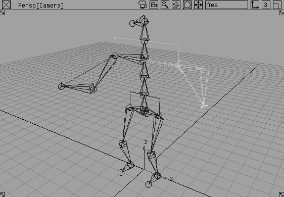
 Select Objects Add IK handle. Click the shoulder joint of the left arm to make it the root of the IK chain.
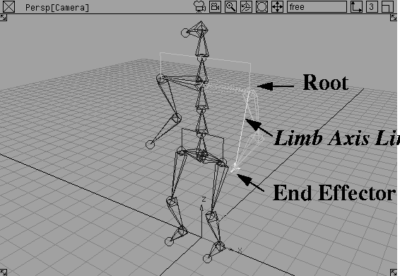
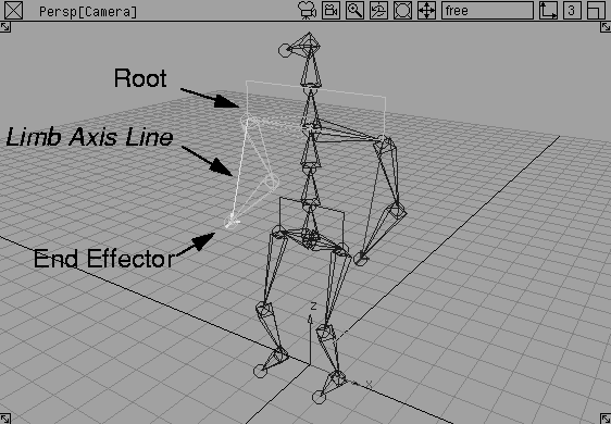
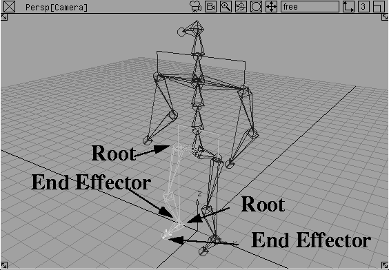
You have now applied a single chain IK solution to the left arm. Connecting the Root and the End Effector is a yellow line known as the Limb Axis line. This helps you determine the start and end points of the IK chain.
 With Add IK handle still selected, click the shoulder joint of the right arm to make it the root of another IK chain.
You have now applied a single chain IK solution to the two arms. This way, you can animate them by manipulating the IK handles.
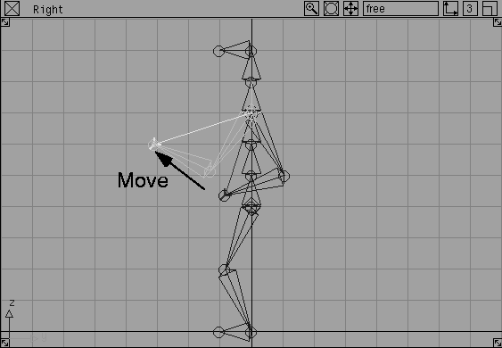
 Select Xform Move. Click-drag in the Right window to move the right arm's IK handle. The IK handle lets you drag the arm. Because the single chain is an analytical IK solution, the motion is fluid and predictable.
 With nothing picked, select Pick IK handle. With the middle mouse button, click the other IK handle.
 Select Xform Move and move it into a new position.
Assume rest pose. The left arm goes back to the rest pose.
Select Xform Move and move it into a new position.
Assume rest pose. The left arm goes back to the rest pose.
| Note: Because only part of the skeleton's hierarchy was picked, only this part returned to the rest position. |
Assume rest pose. The right arm goes back to the rest pose.
The arms use a single IK handle to control motion. To control the legs, you can apply one IK chain from the hip to the ankle and another from the ankle to the toe.
Nothing.
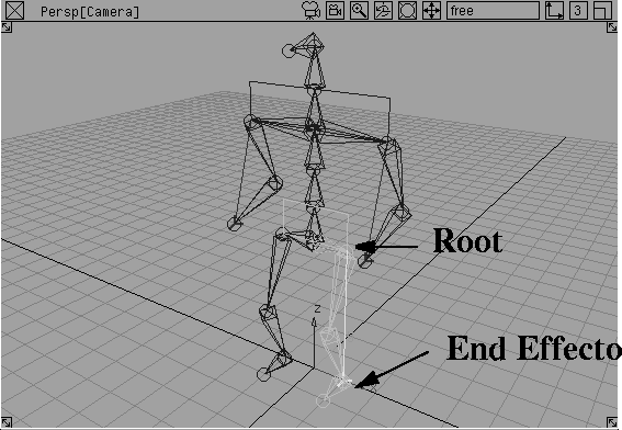
 Select Objects Add IK handle. In the Perspective window, click the hip joint of the left leg to make it the root of the IK chain.
 With Add IK handle still selected, click the ankle joint of the left leg to make it the root of the IK chain.
You have now applied a single chain IK solution to the leg and the foot.
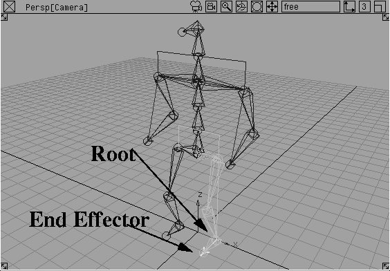
 Select Pick IK handle and click-drag a pick box with the middle mouse button over the two IK handles on the left leg.
 Select Xform Move. Click-drag in the Right window to drag the end effectors belonging to the leg and the foot.
Because you have used an extra IK handle on the foot, notice how the foot maintains its angle with the ground. In the next lesson, you will learn how to use constraints so that you can rotate the two IK handles as if they make up a single foot.
Assume rest pose. The character goes back to the rest pose.
 Use Add IK handle to add IK chains for the right leg and the right foot.
While manipulating the IK handles, you may have noticed that the elbow and the shoulder joints have a great deal of freedom. While this freedom is preferable in most situations, you also have the ability to restrict some of the motion by setting limits to some of the joints.
You can set limits to the knee or ankle joints which lie within the IK chain. You can't, however, set limits to the hip joint, which is the root joint. The root needs 360 degrees of freedom in all three directions in order to solve properly.
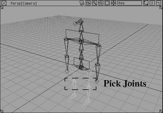
 Select Pick IK handle and click-drag a pick box with the middle mouse button over the right leg's two IK handles.
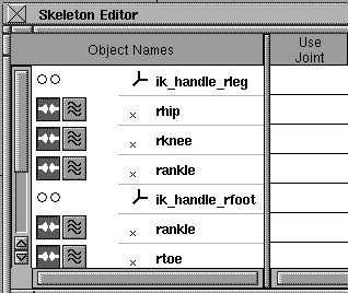
Skeletons.... From the Editor's List Mode menu, select Picked.
Select Pick IK handle and click-drag a pick box with the middle mouse button over the right leg's two IK handles.
Skeletons.... From the Editor's List Mode menu, select Picked.
| Note: The order of the listing of joints may be different than what is shown. |
ik_handle_rfoot. Use the same method to change the other joint names. Rename the other ik handle and its joints (as shown in the following).
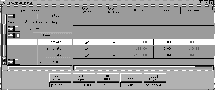
Note: In order to set rotations, you must click X rotate to highlight the row in white, as shown below. |
Use Limits column along the X rotate row.
Notice that the Minimum and Maximum rotational limits columns become un-grayed. This lets you type in values for the minimum and maximum rotations directly or you can set them in a more interactive manner.
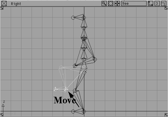
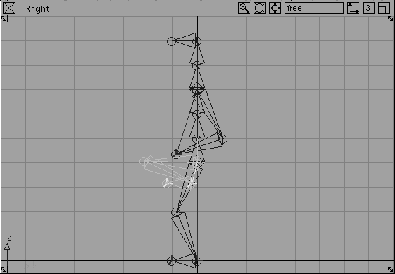
 Select Xform Move. In the Right window, click-drag until you're satisfied with the rotation of the knee.
X rotate in the Skeleton Editor.
| Tip: The name must be highlighted if you want to set a value on the channel. |
Minimum. This sets a minimum angle.
 Select Xform Move. In the Right window, click-drag to move the end effector.
| Note: The knee will stop rotating when it hits the maximum angle. You could also set limits for other joints. |
You cannot set limits for the hip joint or the ankle joint because they are root joints and need at least a full 360 degrees of motion.
| Tip: You may find that the leg stops too harshly and you don't want to use limits. In this case, simply make sure that you don't create exaggerated leg positions while keyframing. |
Assume rest pose. The character goes back to the rest pose.
Skeleton Editor.
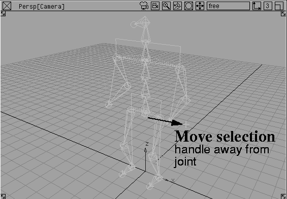
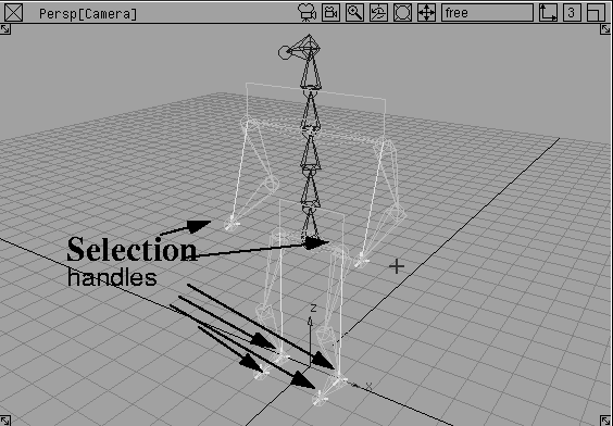
Before you begin animating the skeleton, you can use a general type of selection handle to improve the upcoming workflow. Since you are working with IK handles and joints, you would find yourself switching back and forth between these two pick modes.
You can apply general selection handles to any dag node. The advantage of this is you can use a single pick mode (Pick Object Types Selection handle) while keyframing to streamline the workflow.
 Select Pick Object. Click on any of the skeleton's joints with the middle mouse button to pick the whole skeleton.
 Select Xform Local Move selection handle. In the Perspective window click-drag with the left mouse button to move along the X axis.
| Tip: You can separate the handle from the actual joint so that it is easier to see. This is not necessary but you may find it easier to see the handles. |
 Select Pick Nothing, then select Pick IK Handle. Click-drag a pick box over all the IK handles.
| Note: It would seem that putting a selection handle on an IK handle would be redundant. Now you can use the Generic selection handles to pick both IK handles and joints using the same pick mode. |
| Tip: If you want, you could use the Move Selection handle tool to move the handles outside the character. For now, leave them where they are. |
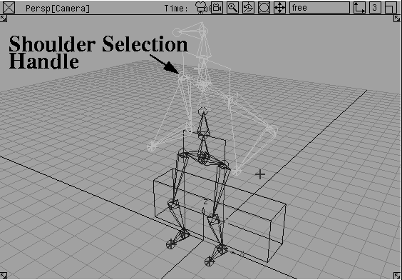
 With nothing picked, select Pick Joint. Click the joint between the shoulders at the base of the neck.
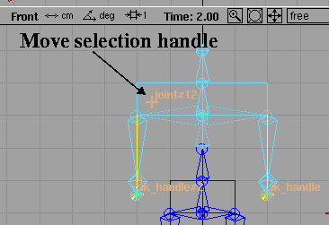
 Select Xform Local Move selection handle. In the Front window click-drag to place the selection handle just above the character's right shoulder.
 Select Pick Nothing, then select Pick Object Types Selection handle. With the middle mouse button, click the different selection handles to see how you can now pick both IK handles and joints with this pick mode.
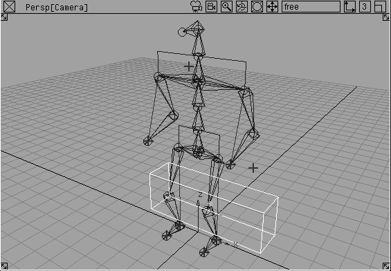
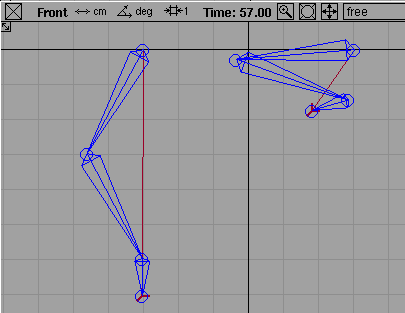
The next part of this lesson involves animating the skeleton so that it starts in a standing position and then sits down on a bench.
 Select Objects Primitives Cube. In the Right window, press the
 Alt key and click the grid square to the right of the character and one grid square above the ground line.
 Select Xform Nonp scale. Enter
 6, 1.5 2 to scale the cube into a bench-like shape.
 With nothing picked, select Pick Object Types Selection handle. With the middle mouse button, click the selection handle that belongs to the top node (the hip joint) of the skeleton hierarchy.
 Select Xform Move. Click-drag in the Right window to move the skeleton to the right, over the bench.
| Note: You cannot move the skeleton to a sitting position. |
Shift key and the middle mouse button to click-drag a pick box around all the selection handles to pick them.
Note: Because the current pick mode is Selection handle, you can pick the handles by pressing the Shift key while using the Move tool. |
0 in the time slider. From the Animation menu, select Set keyframe.
Keyframes are set for all the handles at frame 0.
 Select Xform Move. Click-drag in the Right window to move the hips to a sitting position.
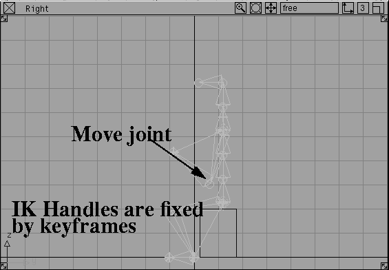
With keyframes set, the IK chains can work backwards. This lets you animate the body and have the arms and legs remain planted in their keyframed positions.
0 as the current frame in the time slider to re-load this frame and reposition the character standing up.
To animate the character, continue to set keyframes on joints and IK handles. In this case, the character will look to the left and right before extending hands and sitting down.
15.
 Select Xform Rotate. Click-drag with the right mouse button and rotate the shoulders to the character's right.
30.
 With Xform Rotate still selected, click-drag with the right mouse button and rotate the shoulders to the character `s left.
40.
 With Xform Rotate still selected, type
 0 and press Enter to rotate the shoulders back to a straight position.
These keyframes create a motion where the character looks around the room before sitting down.
Now, set keyframes on the top node of the character and on the IK handles themselves. Animate the character sitting down with arms stretched back to break the fall.
40.
75.
 Select Xform Move. In the Right window, click-drag the character into a sitting position.
Shift key and the middle mouse button, click-drag a pick box around the two handles belonging to the character's arms.
38.
65.
 Select Xform Move. In the Right window, click-drag the hands down to the bench to help break the fall. This motion will also anticipate the sitting motion.
To complete the character animation, you should add some outward rotation to the arms while they absorb the impact of the character's sitting motion.
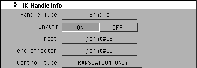
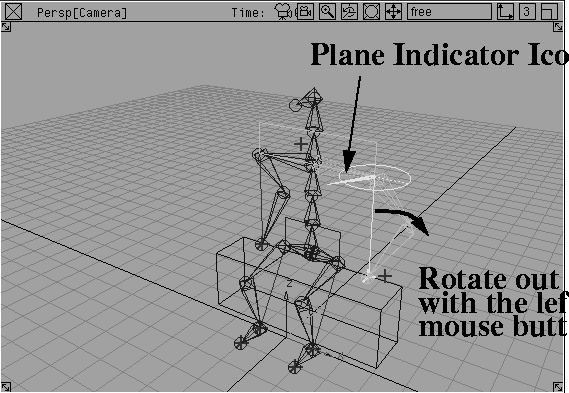
All IK chains lie on a plane that cannot, by default, be rotated. You can now use the Information window to change the control type of the IK handles and control other types of motion such as the rotation of the plane.
Information window.... In this window, open the IK Handle info section. You can see that the Handle Type is Single and the root and end effectors are defined.
Also, notice that the Control type is set to Translation Only. By default you can only translate IK handles with no control over the plane of the IK solution. This makes IK easier to use but can limit the ability to achieve certain types of motion.
Control type pop-up in the Information window, select Plane Rotation.
In the modeling views, a circle and a Plane Indicator icon appear on the root of the IK chain. These new controls let you rotate the plane of the IK chain using the left mouse button in combination with the Rotate tool.
Note: The third Control Type is called Plane/ Pole rotation. This Control Type lets you control the chain's Pole Axis, which helps you deal with extreme types of motion where the IK chain may flip. If you encounter flipping, then you can find out more about this Control Type in Animating in Alias. |
Control Type to Plane Rotation.
65 in the Time slider.
Yes when asked to overwrite keyframes.
78.
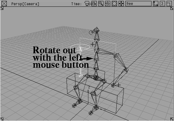
 Select Xform Rotate. Click-drag with the left mouse button and rotate the left arm until its plane is rotated out from the body.
Yes when asked to overwrite keyframes.
 Select Xform Rotate. Click-drag with the left mouse button and rotate the arm until its plane is rotated out from the body.
sitting_01.
This completes the basic setup of a skeleton animation. If you don't like the motion, you can work with the keyframe tangents in the action window or apply other keyframing techniques to improve the quality of motion. Use this skeleton to explore some of the keyframing possibilities.
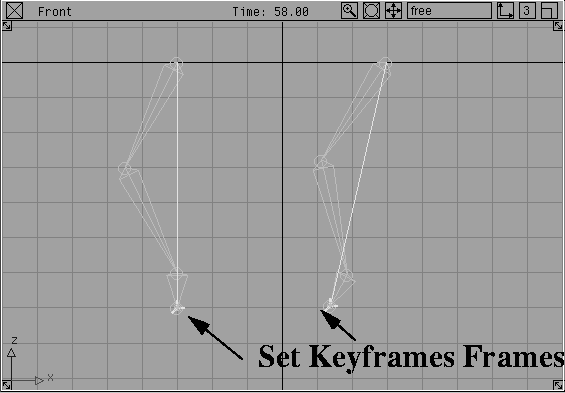
Before going to the next lesson, you should take a closer look at how a skeleton's rest pose affects the quality of motion generated by the single chain solution. Using two IK chains with different rest poses, you can explore how rest poses affect the character's motion.
 Select Objects Draw Skeleton.
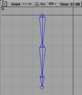
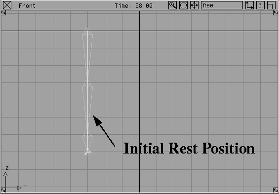
Alt key to use grid snapping and place four joints. Place the first joint at 0, -3. Place the second at -3, -3. Place the third at -6, -3. Place the fourth at -7, -3.
 Select Objects Add IK handle.
The sitting man's IK chains only contained one internal joint. In this example an extra joint is added to show how a chain that spans three bones reacts to its rest position. In the earlier example, the IK chains only spanned two bones and the rest position had less influence on the final result. The rest position is most important with a chain that spans three or more bones.
You'll now move the IK handle on this bone, then duplicate it to create different rest positions. Each will create a different kind of motion when animated.
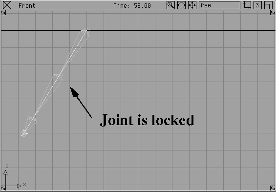
 With the IK handle active, select Xform Move and click-drag to move the handle.
| Note: The lowest joint moves but the middle joints are locked up. This is because the rest position doesn't include any rotation, so the IK chain can't decide which direction to go. |
Assume rest pose.
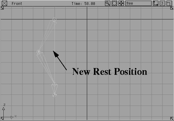
 Select Pick Joint and with the middle mouse button click the second joint from the top of the chain.
 Select Xform Local Set Pivot and click-drag with the middle mouse button to move the joint to the left.
| Note: Since Set Pivot does not affect joint rotation, you don't need to set a new rest position. The rest position must only be reset if the joints have been rotated by either the Rotate tool or a dragged IK handle. |
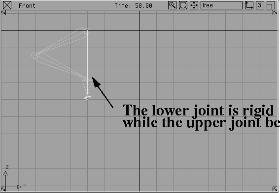
 Select Pick IK handle and use the middle mouse button to pick the handle.
 Select Xform Move and click-drag the end effector to move the handle.
| Note: This chain now bends at the upper joint in an appropriate way. At the same time, the lower joint remains fairly rigid because it is locked by its rest position. |
 Select Pick Object and with the middle mouse button, click the top joint of the chain.
 Select Xform Move. Using the middle mouse button, click-drag to move the chain to the right.
 Select Xform Rotate. Using the middle mouse button, click-drag to rotate the knee joint up.
Shift and the Down arrow buttons to move the lower joint. Rotate this joint. Do the same for the other joints until the skeleton appears as follows:
 Select Pick Object. With the middle mouse button, click the top joint of the duplicated leg.
Set rest pose. Since the skeleton was edited using the Rotate tool, a new rest position has to be set
Select Pick Object. With the middle mouse button, click the top joint of the duplicated leg.
Set rest pose. Since the skeleton was edited using the Rotate tool, a new rest position has to be set
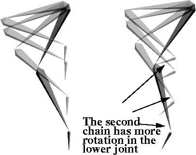
| Note: The two Rest positions will animate differently. The Rest position of the duplicated leg will put more rotation in the ankle joint. |
 Select Pick IK handle. With the middle mouse button, pick the IK handle on the duplicated leg.
 Select Xform Move and click-drag on the end effector to move the handle so that it looks like the original leg. As you will see, this chain has more rotation on the ankle joints.
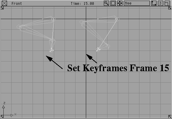
The best way of comparing the results of changing the rest positions is to animate the two chains and compare their motion.
 Select Pick IK handle. With the middle mouse button, click-drag over the two IK handles.
0.
 With Xform Move, drag the two IK handles into a new position.
Min/Max as the preview range.
Play button to preview the motion.
You will see that the first solution is locked just above the end effector while the second solution has more rotational freedom.
By setting different rest poses, you can change how the IK chain solves. This in turn affects the quality of the resulting motion. While no one solution is particularly better than another, you may want to test several rest poses to find the one that best suits the particular animation needs.