To familiarize yourself with the Alias Modeling Environment you'll create a Greek-style temple using Primitives. This will give you experience placing objects into a 3D scene and moving, scaling, and rotating them using the Xform tools.
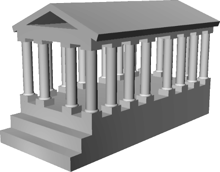
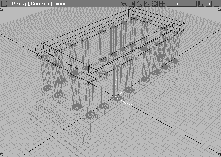
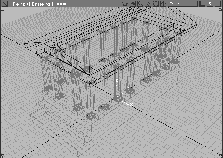
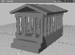
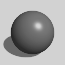
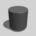
The rendering below shows how primitives are used in the construction of a temple. You build the base using cubes, and construct columns using cylinders and spheres. The roof is created using several scaled and rotated cubes.
In this lesson, you place and scale objects in 3D space with the mouse and keyboard input. For most of the lesson, you use the mouse. The mouse may be less accurate, but it lets you work interactively. As you place the objects in 3D space, refer to the four views to ensure correct positioning.
If Alias is already running on your machine, you can either save or delete current work.
Double-click on the Alias icon in your workspace. If Alias is already running, go to the File menu and select New. If prompted, click Yes to delete the current stages.
Tip: It is a good idea to start your projects with four windows because you can see your work from all points of view. If your window setup does not show four windows, choose Layouts  All windows All (User Defaults). All windows All (User Defaults). |
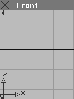
The Alias environment should have a Z-up orientation, because this lesson requires numeric input. Z-up orientation will ensure that the numeric input in this lesson works correctly. Orientation is displayed in the lower left corner of the front window.
If the arrow pointing up is labeled Z, the orientation is already Z-up.
If it is labeled Y, change it by going to the Preferences menu, and selecting User Options Alias Preferences. In the option box, set the Coordinate system to Z-up.
| Note: To accept this change, you must exit and relaunch Alias. |
The temple is built from the ground up. The base is constructed first, with a cube primitive that is scaled and moved into place.
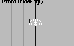
 Select Objects Primitives Cube.
0, 0, 0 in the command line and then pressing the Enter key. Note that you can place an object into the workspace without using the mouse.
Tip: You can enter XYZ coordinates as 0, 0, 0 or 0 0 0 and then press Enter. |
If the Y and Z values are 0, type only 0. Alias automatically assigns zero to Y and Z when you press Enter.
The cube still needs to be scaled and moved in order to look like the temple base.
|
Important: Objects Primitives Cube is still set. Be careful not to click in a modeling view, or you'll create a second cube. If this happens, select Del active from the Delete menu. |
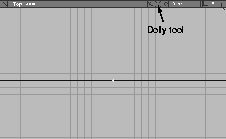
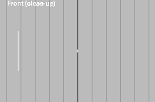
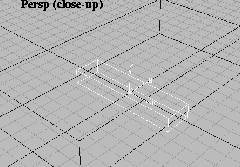
Dolly tool toward the left, to dolly out. Stop when there are about 10 grid squares above and below the X-axis.
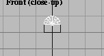
 Select Xform Nonp scale. Click-drag using the left mouse button in open space without touching the cube.
| Note: You can change the scale of the object in both the X and Y directions by clicking with the left mouse button. Also, Xform tools stay selected until you choose another command. |
You do not need to click on an object to transform it with Xform tools. Once it has been selected, click-dragging transforms it interactively.
 With Xform Nonp scale still selected, click-drag vertically with the right mouse button. Scale the cube to a height of about 3 units.
Nonp scale tool still selected, Alias prompts you to enter scaling values. For exact scaling in the X,Y and Z directions, type
With Xform Nonp scale still selected, click-drag vertically with the right mouse button. Scale the cube to a height of about 3 units.
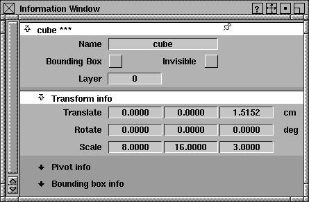
Nonp scale tool still selected, Alias prompts you to enter scaling values. For exact scaling in the X,Y and Z directions, type 8, 16, 3. This creates an appropriate base. (Don't forget to press Enter.)
Note: The [ABS] at the end of the prompt line indicates Absolute mode. In this mode, scaling is based on the actual measurements input. 8, 16, 3 scales it to a size of 8 units x 16 units x 3 units. |
You can now work with objects using both mouse movements and keyboard input. You can also use either method to move the base.
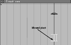
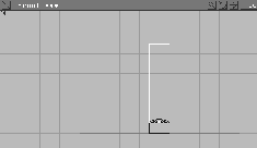
When you move an object, you are actually moving its pivot point. The pivot point of the base is at its center. The temple base is moved so it sits on the ground surface (the X-axis).
 Select Xform Move.
Notice that when using the right mouse button, the movement is again restricted to the vertical dimension.
Information window... from the Windows menu. Click the Transform info submenu.
Note: These values are useful in confirming the exact position of a model and in refining its transformations. The Translate, Rotate and Scale factors of the object are shown. The Scale values are 8, 16 and 3 (the same as were set earlier using Xform Nonp scale). |
The third box shows the Z coordinate of translate. This is the amount it was moved along the Z-axis with the mouse.
1.5, and press Enter to round it off. Click on the close box in the top left corner of the window.
Dolly tool.
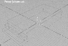
Tumble may help to center the temple.
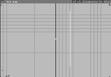
The grid helps you place objects accurately into the scene using the mouse. To place the next object at the origin, you can temporarily turn on grid snapping using the Alt key.
 Select Objects Primitives Cube and press and hold the
 Alt key.
Alt key temporarily turns on grid snap and ensures that the cube's center or pivot is placed at the origin. Release the Alt key.
 Select Xform Nonp scale and type
 8, 2, 1 and press Enter. This scales the cube about the pivot by a value of 8 in the X direction, 2 in the Y direction and 1 in the Z direction.
| Note: Grid snap was not used to scale the cube since it applies only to the positioning of an object's pivot point. |
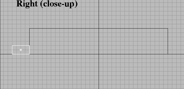
You can move the temple step with grid snap, but the current grid spacing does not have small enough increments. To fix this, you change the grid spacing.
By changing the grid spacing to half its original size, you can move the first step accurately and then place the second step correctly in the Front window.

 Select Grids Grids Grid spacing.
0.5 and press Enter. The grid spacing changes to half its original size.
| Important: Do not click-drag while this function is selected because it will interactively change the grid spacing. |
 Select Pick Object to exit the
 Grid tool without unpicking the temple step. This insures that the grid will not be modified inadvertently.Dolly tool in the Right window title bar, zoom out until the base has about 5 grid squares on each side.
 Select Xform Move.
Alt key to temporarily turn on grid snap and drag in the Right window with the left mouse button so that the cube sits exactly in front of the temple base and on the ground surface. Release the Alt key.
Note: Although you can turn Grid snap on permanently, the Alt key lets you temporarily turn snapping mode on or off. |
 To create the middle step, select Objects Primitives Cube.
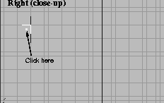
Alt and click one grid square above the first step and one grid square to the left of the base. Release the Alt key.
 Select Xform Nonp scale and type
 8, 1, 1 to scale the step. Remember, you must use keyboard input to scale accurately. Grid snap does not work with scaling.
 Select Pick Object Types All obj/lights to pick all geometry. From the ObjectDisplay menu, select Template to create templated geometry.
| Tip: When geometry is templated, it cannot be accidentally altered, but can still be viewed or deliberately changed as you work on your model. |
 Select Grids Grids Grid preset. This resets the grid to its default setting.
Save your model. Be sure to save your work at regular intervals. In some cases you may want to save versions of your work under sequential names such as file01, file02, and so on. This allows you to keep track of your design process.
| Note: A wireframe icon of the model is created for each file saved. This icon is a miniature of the image in the active window. As a result, you may want to select the Perspective window before you save so the icon best reflects the model. |
From the File menu, select Save as. Enter temple_01 in the field beside File and click on Save Wire.
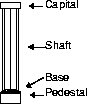
A column combines several primitives-a half-sphere for the base, a cylinder for the shaft, and cubes for the pedestal and capital. You place the primitives, scale them, and move them into final position, just like the temple base. Once you build the first column, you can duplicate it to create the rest of the columns. Primitives are often used in this manner.
As you build the column, you will also look at the difference between Absolute and Relative values.
 Select Objects Primitives Cube.
0, 0, 3.25 to position the cube. (Don't forget to press the Enter key when using keyboard input.)
 Select Xform Nonp scale and type
 1, 1, 0.5 to scale the cube. Press Enter.
 Select Objects Primitives
  and type
 180 degrees for the Sweep. Click Go.
Alt to temporarily turn on grid snap and click on the grid square at the base of the column in the Front view. This places the sphere on the grid.
 With the half-sphere still active, select Xform Move and enter
 0, 0, 0.5 to move it on top of the column base.
Note: The half-sphere has moved towards the ground, to the coordinates of 0, 0, 0.5. Remember, in Absolute mode all transformations are applied to the object as it exists at the origin. |
 Select Xform Move and type
 r 0, 0, 0.5. The half-sphere moves above the column base.
| Note: In Relative mode, the transformation is applied to the current position of the object. This time, the 0.5 Z transformation came from the existing position instead of moving the sphere to an absolute coordinate of 0.5. |
 With the half-sphere still active, select Xform Nonp scale. Enter
 1, 1, 0.4 to scale the sphere in the Z direction. Relative mode applies this scale factor to the existing dimensions.
The main body of the column is created with a cylinder. By default, the pivot points of primitives lie at their centers. By moving the pivot, you can change how the cylinder scales.
 Click in the top window to activate it. Select Objects Primitives .
Sweep, type 360 degrees and press Enter. Click Go.
Alt to turn on grid snap temporarily and click on the origin in the Top window.
| Note: Although you can place cubes in any window with the same results, you must place cylinders in the window where their circular ends should be. Since the temple has vertical columns, place the cylinder in the Top window. |
 Select Xform Local Set pivot. Type
 0, 0, -0.5 to align the pivot point with the bottom of the cylinder.
 Click in the Front window to activate it. Select Xform Move.
 Select Xform Nonp scale. Click-drag upwards with the right mouse button to scale the column to a height of about 4 units.
 With Xform Nonp scale still selected, type:
 0.8, 0.8, 1.
By staying in Relative mode, you can preserve the column height while scaling other dimensions with keyboard input. The same input in Absolute mode would change the column's height to 1 unit.
| Note: In your own work you may decide to work more interactively using the mouse or more accurately using keyboard input. You can use the mouse to quickly sketch a design or build an animation object for visual impact. On the other hand, you may be preparing a model to a specific size or for CAD output, which would require greater accuracy. |
You can copy the base of the column to create the top part. Copying and modifying existing geometry is often easier than creating new primitives and having to redo the same transformations.
 Select Pick Nothing to de-select all objects.
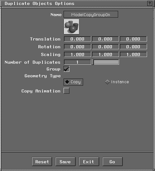
 Select Pick Object and click on the cube at the base of the column.
from the menu. The
Select Pick Object and click on the cube at the base of the column.
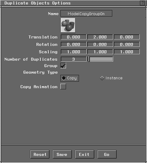
from the menu. The Duplicate Objects Options box appears. Click on the Reset button to make sure that the Translation, Rotation and Scaling factors are set to their defaults. Click Go to make a single copy of the selected piece.
 The duplicated cube currently sits on the original. Select Xform Nonp scale. Type
 a 1, 1, 0.3 and press Enter.
| Tip: The "a" returns you back to absolute values. Because you wanted to scale the copied cube to a specific scale, you entered dimensions in absolute mode. |
 Select Xform Move. In the Front window, click-drag up with the right mouse button.
Once grouped, the individual objects are placed under a new node that can be copied and moved as a single object. Grouping objects is an essential modeling technique. It is also an efficient way to structure and control your geometry.
 Select Pick Nothing to deselect all geometry.
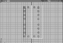
 Select Pick Object. Using the mouse, click-drag a pick box around the four column pieces. Once selected, they become active.
The group now displays a single pivot point at the origin. (However, individual pivot points are preserved for each component). In this case, the pivot point is at a height of 0 although the column sits 3.0 units above the ground. This means that you won't need to change the Z translation value when you move the grouped object.
 Select Xform Move. Type
 -3.5, -7.5, 0 and press Enter to position the column at the corner of the base.
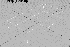
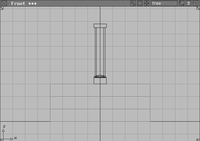
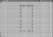
In the Perspective window, your model should look like this:
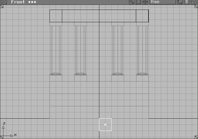
By copying this column, you can create the other temple columns. The first copy is positioned with grid snap. After half of the columns have been built, you can use mirroring to complete the rest.
 Select Grids Grids Grid spacing from the menu.
0.5 and press Enter to reset the grid interval.
Grid button at the upper right corner of the screen to turn it on.
Tip: Although the Alt key turns on grid snap temporarily, you can keep grid snap on with this button. |
 Select Xform Move. In the Top window, click-drag left with the middle mouse button using grid snap to move the column 2 units (or 4 grid lines) to the right.
| Note: Remember that the grid was set to 0.5. |
 Now select Xform Move. Click-drag left with the middle mouse button to move the columns 3 units (or 6 grid lines) to the right. Repeat this step to copy the fourth column and move it another 2 units (or 4 grid lines) right.
 Select Pick Nothing.
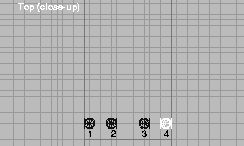
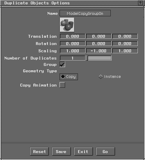
 Select Pick Object. Click on the two outer columns (that is, 1 and 4). From the Edit menu, select Duplicate object-. Type
 Translation factors of 0, 2, 0. Type 3 in the Number of Duplicates field. Click Go. Columns 1 and 4 are each copied 3 times.
 In the Top window, select Pick Nothing and then Pick Object.
| Note: You must group the columns. If you don't, the columns mirror around their existing pivot points, placing them on top of the original columns. |
. Click Reset to return values back to their defaults. Type Scaling values of: 1, -1, 1.
| Note: The temple columns were created using the Duplicate object function. This function can create single copies, or transformed (moved, scaled, rotated) multiple copies. Notice how the columns were first grouped to set the pivot point at the origin. |
 Select Pick Object and click on the original group of columns to make it active.
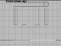
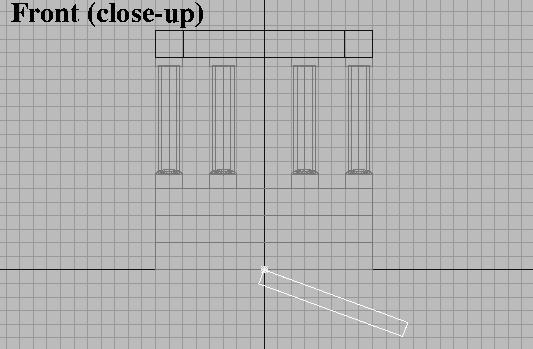
The next part of the temple is the box-like structure supported by the columns. In architectural terms, this is the entablature.
To create the entablature, a cube primitive is built, scaled, mirrored and rotated into place. Once again, you can use the mouse to position the cubes, relying on multiple windows to ensure accurate placement.
 Select Objects Primitives Cube.
Alt key.)
Note that forgetting to turn grid snap off could cause confusion later. Also, note that you can turn off grid snap temporarily by pressing Alt while grid snap is on.
 Select Xform Nonp scale and type
 8, 1, 1 to resize the cube.
 Select Xform Move. In the Front window, click-drag with the right mouse button to place the cube above the columns.
| Tip: When positioning objects in 3D space, you should refer to at least two windows. |
 Select Xform Local Set pivot and type
 0, 0, 0 for the new pivot position.
.
. The Duplicate option box appears. Click on Reset to return to default values. Type Rotation values of 0, 0, 90. Click Go.
 Select Xform Move. In the Top or Front window, click-drag with the middle mouse button to move the cube above the side row of columns.
 Note that the pivot point has moved. To return it to the origin, select Xform Local Set pivot and type
 0, 0, 0.
 The cube is too short. To correct this, select Xform Nonp scale. In the Top window, click-drag with the middle mouse button until the cube touches both ends of the other beams.
| Note: Because the cube has been rotated, the middle mouse button restricts scaling along its own length. Before rotating an object you should make note of mouse button constraints because even though the object has been rotated, the original button constraints are still in effect. |
. The Duplicate Objects Options box appears.
Rotation values to 0, 0, 180. Click Go.
| Tip: Since the beam is a simple shape, a 180 degree rotation is the same as mirroring the objects. |
The final part of the temple is the roof. Once again, it is created out of a cube primitive that is scaled and rotated into place. First, you move the cube's pivot point so it can accommodate the scaling and rotation needed to create the roof slab.
 Select Objects Primitives Cube. In the Front window, press the
 Alt key and click one unit right of the origin and one unit below the ground plane. If you place the cube now, you can easily reset the pivot point.
 Select Xform Local Set pivot. Type
 0,0,0 to set the pivot point at the upper left corner of the cube. Select Xform Nonp scale. In the Front window, click-drag with the middle mouse button to scale the cube past the edge of the temple by about 3 grid squares.
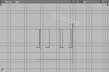
 Dolly the Front view so you can see more space around the temple. Select Xform Rotate.
| Note: The Rotate tool has its own mouse button conventions. The left mouse button rotates around the X-axis, the middle button rotates around the Y-axis and the right button rotates around the Z-axis. |
 Select Xform Move. In the Front window, click-drag with the right mouse button to move the roof slab up to the top of the temple.
. Duplicate and rotate the roof slab 180 degrees just like the entablature beam created earlier.
Select Xform Move. In the Front window, click-drag with the right mouse button to move the roof slab up to the top of the temple.
. Duplicate and rotate the roof slab 180 degrees just like the entablature beam created earlier.
After untemplating the base and the columns, you can evaluate the wireframe model by quickrendering in the Perspective view.
 Select Pick Nothing to deactivate any active geometry.
 Select Pick Template. Click-drag a pick box over the model to pick templated geometry, and from the ObjectDisplay menu, select Template to untemplate it.
Congratulations! You have just completed your first modeling project using Alias. In this lesson you have learned how to: