Welcome to Alias Version 9.0. In the following lessons, you will learn how to model, render, and animate in a 3D workspace. To begin, you will learn about the Alias user interface (UI), which gives you access to tools and menu functions.
The Alias UI has been designed to let you control the way you want to work. You can access the Alias functions using several methods, including menus, hot keys, iconized tools, and the tool shelf. This lesson lets you explore Alias' powerful and flexible UI so you can increase your productivity.
When you first start using Alias, the process of customizing may seem to slow you down a little. However, this feeling will go away once you prepare your personalized UI, and can access the tools you need quickly and easily.
If you are new to the UNIX world, you first need to log into your system. To begin, log into the user account that has been set up to run Alias.
In the IRIX start up screen, type your user name in the account name field and press the Enter key. In the password field, enter your password and press the Enter key.
| Note: A user account must be set up in a specific manner to run Alias. Your system administrator must prepare your account according to the instructions set out in the Installation Guide. |
Alias can be started either directly from a UNIX shell or the IRIX workspace. The result is the same for both methods.
Alias and press the Enter key.
Find an Icon option. The Find an Icon window appears. Type in Alias and press the Enter key to find the Alias icon.
Once the Alias icon has been located, drag it from the picture window onto the workspace. For more information about icons and how to move them around the IRIX workspace, consult your SGI documentation.
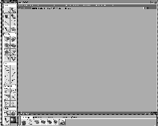
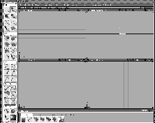
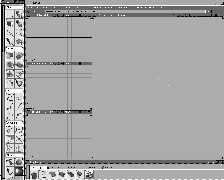
When launched, Alias shows a menu bar at the top, a tool palette at the left, and the tool shelf at the bottom of the screen. There are no working view windows, so you cannot immediately begin drawing in 3D. You will create view windows as you explore how the menus work.
Menus in Alias follow the Motif standard that will be familiar to those of you who have worked with other programs on your SGI system. Menus contain those Alias functions that do not result in direct manipulation in the 3D modeling world.
When you choose menu functions, you can either use the click-drag approach or the posting approach. The first method is faster, but the second gives you more time to think about your selection.
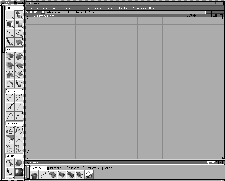
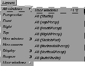
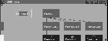
With these menus, you can open several view windows to look into the virtual 3D environment where models are built and animated. In Alias, view windows are treated like objects, and can be saved or deleted.
Yes to complete the action. The four view windows are removed.
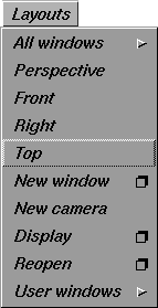
 All (Vertical/Persp). This creates a new window layout that shows the three orthographic windows at the left with one large Perspective window at the right.
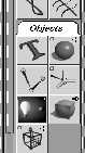
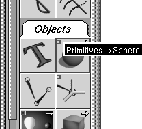
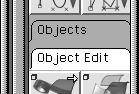
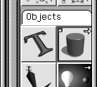
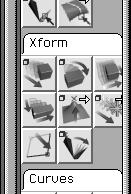
The Tool Palette contains those tools that require direct manipulation in the view windows. Alias has a large number of tools that can be found under various subsections within the palette.
| Note: Depending on which Alias product you are working with, the Objects section shown above may include more tools than you see on your screen. Alias products include many common tools, but some tools are only available to specific products. |
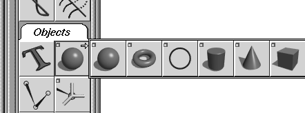
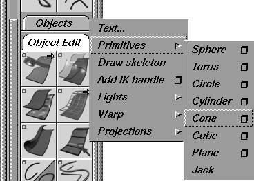
You can see that it is the Sphere tool and the path is Objects Primitives. You can use the middle mouse button to help you learn the meaning of the tool icons.
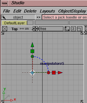
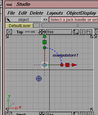
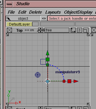
| Note: All primitives appear on the screen with an attached manipulator. Use this manipulator to immediately move, scale and rotate the object into position. For more information, see What's New in Alias. |
| Tip: One method for working is to close all these tabs and open them as needed. When you exit, the status of the tabs is saved for the next time you launch Alias. This way, you can decide if you like them open or closed and the system will remember your preference. |
| Note: You have just used two methods for picking tools from the Tool Palette. Throughout Learning Alias, you will be asked to pick tools in the following manner: |
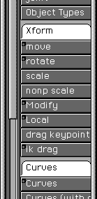
Select Objects Primitives Cube.
When you encounter this statement, you can choose either the menu method (by clicking on the Objects tab) using the right mouse button, or you can find the icon and click on it. A picture of the icon is placed next to the statement to help you identify it.
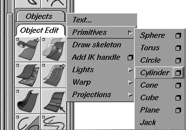
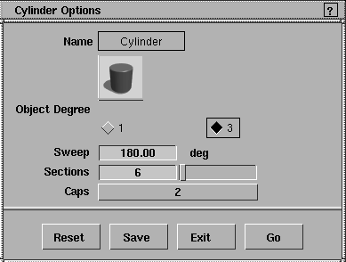
 ) next to Cylinder to open the
 Cylinder options.
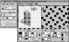
Sweep and change the angle to 180 degrees. Change the Sections to 6.
Tip: Once you type in new information, remember to press the Enter key. |
Save. This saves your settings without actually using the chosen tool. To use the Cylinder tool, you would have to click Go.
Sweep angle back to 360 and the Sections to 8.
Tip: Since this is the default setting, you can also click on the Reset button to get the same result. |
. Click in the Top window to place the cylinder into the scene.
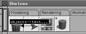
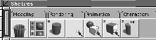
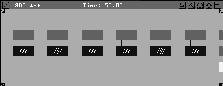
Now that you know where the tools are and how to access them, you can begin looking at the Tool Shelf. At first, this window seems to be a duplicate of the Tool Palette. The difference is that while the tool locations are predetermined in the Tool Palette, you have control over their location in the Tool Shelf.
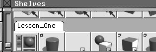
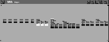
The default Tool Shelf has several shelves with a number of tools. The shelves shown in these illustrations may even differ from the shelf that comes with your version of Alias. Because you can customize the shelf for your own purposes, you can expect it to change a lot as you become more familiar with its capabilities. In the end you will find this to be a very powerful tool for streamlining the user interface to suit your personal requirements.
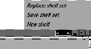
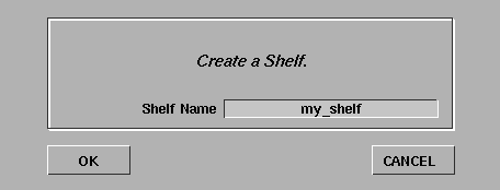
New shelf name window, enter my_shelf and click OK. A new shelf is created.
| Tip: Use the red arrows below the name box to place the tool. Drag the red arrows below the name box onto the shelf area or onto the tab of the shelf you want to place the tool on. |
my_shelf and let go.
| Tip: To move an icon to another shelf, you can drag the name box onto the tab for that shelf (even if the shelf is not highlighted). |
OK. The shelf is renamed.
Nothing, Pick Object and Pick Component tools. Drag these down to the Lesson_One shelf. You will use these tools later in the lesson, so you can keep them on the shelf.
Sweep to 180 degrees and click Go. You now have two Cylinder icons in the shelf that create different types of cylinders.
| Tip: The Tool Shelf versions of the tools will keep your chosen settings, no matter how you change them in the Tool Palette. |
Alt key and double-click on the new cylinder icon. After a short delay, a paint program called xpaint opens with the loaded cylinder icon.
| Note: This utility is "donateware" and is not a supported Alias|Wavefront application. Please refer to the application's online help for any information about the product. |
OK. Quit the xpaint program.
| Note: This labeling process can only be applied to tool icons that are on the shelf. The actual tools in the Tool Palette and the menu function icons cannot be edited this way. |
Throughout the lessons in this book, you are asked to use tools from the Tool Palette. To familiarize yourself with how to use the Tool Shelf, you should build a new shelf for each lesson and delete the shelf when you are finished. Since most lessons contain repeated uses of a few specific tools, you will quickly see how the shelf can speed up your workflow as all the necessary tools are at your fingertips.
Later, you will want to make shelves that fit your workflow and emphasize the tools that you use on a regular basis.
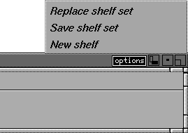
In the option button on the right side of the Shelf window, you will find two options for reading and writing shelves. You may find that you have a favorite shelf setup for modeling that differs from your animation shelf setup. These options let you save Shelf sets.
| Tip: Alias ships with several default Shelf sets based on our research into the tools most frequently used by various types of users. Later, you may want to explore these shelf setups as a starting point for creating your own shelves. |
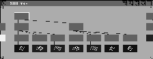
So far, the tools in the palette and shelf have been displayed as medium sized icons. There are several alternative display options that let you see these items as either text or icons of varying sizes. You are in control, since the look of the user interface is decided by you. You can also change the look of the palettes by changing their placement and orientation.
Interface options -. Click the Show Icon Labels option to turn it on. Click Go.
| Tip: The icons now display labels to help you learn the tool names. |
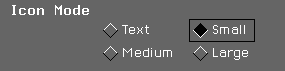
Interface options -. Change the Icon Mode to Small. If you don't need the icon labels, turn the labels off. Click Go.
The tool icons in both the shelf and the palette are now shown as small icons. As you become more familiar with the icons, this icon mode lets you see more tools on the screen at one time.
Interface options -. Change the Icon mode to Text and click Go. The tool icons in both the shelf and the palette are now shown as text buttons.
| Tip: Because of the default configuration of the Tool Palette, the yellow arrows indicating pop-up conditions for tools are not visible. You need to expand the palette to see these arrows. To display the tools in pop-up conditions, simply click and hold. |
Interface options -. Change the Icon Mode to Medium and click Go. The tool icons are back to their default size.
While completing the tutorial lessons, you may want to test which icon mode best suits you and your work.
 This reorients the shelf tabs in a vertical organization similar to the Tool Palette. Use the Scroll bar on the left to scroll between the various shelves.
| Tip: You can position the Tool Shelf and Palette anywhere on the screen using standard Motif window-manipulation techniques. You can have a vertical shelf and a horizontal palette, or you can have both of them vertical. The choice is up to you. Once you position the shelf window in the workspace, you can orient the icons and tabs to suit. As you work, you may want to play with different palette and shelf positions to see which ones you like best. |
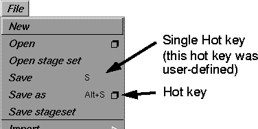
To access tools from the keyboard without using either the palette, menu, or shelf, you can assign single or double key hot keys to any of Alias' tools and functions. Though Alias ships with some preset hot keys, you can add your own from the Preferences menu.
Tip: When using single key hotkeys the status bar initially does not let you enter values. To use the status bar, you must either click in it, or press the Tab key to activate it. |
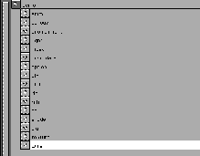
Hotkeys / Menus.... Click on some headings to display their list of tools. You can use this window to add or edit the hot key settings using either single hot keys or double hot keys. From this window, you can also hide tools that you don't use from the interface. To do this, click on the corresponding check marks in the Short Menu Display column.
If you are a new user, we suggest you do not add any hot keys until you are familiar enough with Alias functions to know which tools you may want to access.
| Note: The Learning Alias lessons do not refer to hot keys. If you want to start learning how to use this powerful method of accessing tools, you can set up your hot keys while you are working through these lessons. |
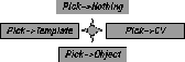
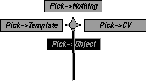
In addition to the shelves and the Tool Palette, Alias includes a special type of menu called a marking menu that gives you fast access to frequently used tools. A marking menu is a floating menu that appears at your cursor when you press the Control and Shift keys in combination with a mouse click.
Note: Marking menus require the use of the Ctrl and Shift keys in a manner that conflicts with the system software's standard use of these keys. You must, therefore, follow the instructions outlined in the Installation Guide to make these keys available for use with the marking menus. |
Ctrl and Shift keys, then click and hold anywhere with the left mouse button. A radial marking menu appears with four tools displayed.
The middle and right mouse buttons bring up different marking menu options. Later you can explore which tools are available in these other two menus.
Object tool is highlighted, and release the mouse button. The black line helps you track the selection.
Ctrl and Shift keys and click drag in an up direction, then quickly release the mouse button. A black line is drawn but no marking menu appears.
You have just used the Pick Nothing tool without actually seeing the tool in the workspace. Once you become familiar with the radial position of the marking menu tools, a quick click-drag gives you intuitive access to these functions.
If you would like to replace one of the marking menu options, you can use the Tool Shelf to create your own marking menu. Please refer to Alias Overview to learn how to customize your marking menus. You can set up menus that contain either 2, 4 or 8 tools. In the case of an 8 tool marking menu, you would drag at angles of 45 degrees to pick the tools.
Alias includes several Delete functions to remove objects, lights and windows from your workspace. These Delete functions clear the workspace so you can retrieve other wire files.
Object and click on the cube. Use either the Tool Palette, Tool Shelf or marking menus to choose it.
Yes to delete the cube.
Object and click on the cone.
Delete key on your keyboard. This evokes the Del active function. At the prompt, click Yes to delete the cube. This is a permanent hot key that you can use to speed up the deleting of objects.
Yes to delete everything from the scene.
| Tip: Since you are about to open a wire file that contains its own view windows, you needed to delete the existing ones. Had you wanted to delete all the objects and lights, but not the view windows, you'd have chosen Del all objects. |
When you work with Alias, set up project directories to keep project info in one place. Each time you start a new project you should create a new directory. For the duration of these lessons, you will work in an existing project directory called CourseWare.
Show List button. You are in the wire directory within the demo project.
wire. A list of directories is shown within the demo project. These directories contain the various files associated with a project. Directories, folders, and files are created for each Alias project.
| Important: These directories should not be deleted or changed because Alias uses them to hold all project files. |
demo. This takes you to the user_data directory where the projects are stored. Click on the name CourseWare to highlight it in white.
Warning: If you do not have a CourseWare project, the CourseWare directory was not loaded with Alias. Consult the installation notes and install this project directory before continuing with the lessons in this guide. Many of these tutorial lessons use supplied files. |
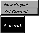
CourseWare project directory selected, go to the Project menu and select Set Current.
This puts the CourseWare wire directory at the top of the lister so Alias can load and save files to CourseWare, automatically. This is very important when working with the Learning Alias lessons. That is, files must be properly referenced to supporting files.
In your own work, keep all the files associated with a single project together.
Now that you are in the CourseWare project, you will open an existing wire file. Wire files contain all the geometry, materials and animation information for your Alias models.
Click the L01_Objects icon in the Lister and then click the Open button. This opens the wire file into Alias.
Tip: You could have also double-clicked on the icon to open the file. Another way to open files is to enter the file's name in the Lister command line and then click Open. |
| Note: For the rest of this guide, the illustrations will focus on the view windows and option boxes. This is because there is no wrong way to set up the user interface. After you customize the UI to suit how you work, the illustrations will still apply. |
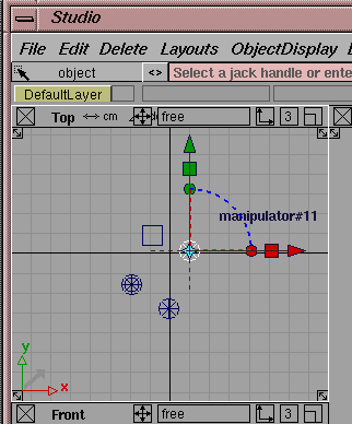
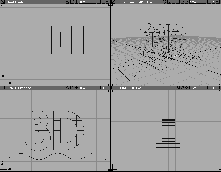
The wire file opens with a standard layout of four view windows. Remember that windows act as objects and can be saved as part of your wire files.
The Perspective window is located at the top right of the screen.
Resize button  with the left mouse button at the bottom left of the window. Drag to make the Perspective window bigger on the screen. Sometimes you need a larger window to work with geometrical details.
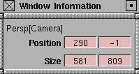
Window Info button  (the third from the right on the window's title bar). This lets you set the Positioning and Size of a window.
Free in the title bar of the Perspective window and drag down to NTSC to size the window accordingly. It is now 645 x 486 pixels. With this menu, you can set your window size to a series of defaults.
645 x 486 and drag down to free: (default). The window is now its original size.
All (Studio) to return the window to its original position.
Next you will import another file "into" the first file, merging them into one file. This can be a useful method of starting with several smaller models that are then brought together into a larger scene.
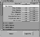
File- . In the
 Wire Options section of the window, set all option buttons OFF. This ensures that you don't place new windows on top of existing windows and that you don't create a new camera.
Warning: It is a good idea to keep the options set to Off when merging files. In the case of Background, for example, you don't want a new Environment shader to overwrite it. |
| Tip: In general, you should only turn on the options that you want to import from the new file. That way, you will not duplicate these entities or override current settings. |
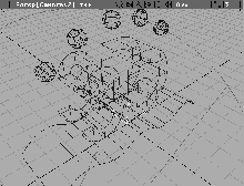
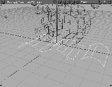
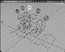
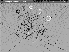
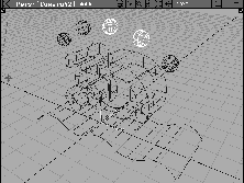
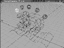
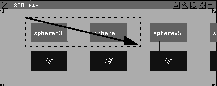
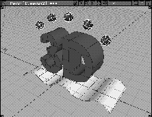
Import File. In the File Lister, click on the file named L01_Objects2, then click Retrieve. This adds five spheres and a light into your existing scene.
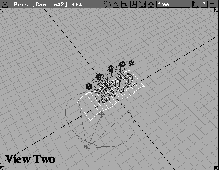
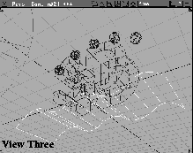
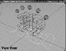
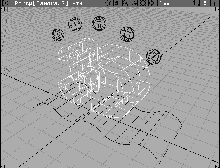
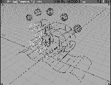
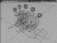
The four view windows display the geometry from several angles. By default, the geometry is seen from the Top, Front, Right and Perspective views. The first three views are orthographic and present a "drafting view" of the geometry. The Perspective view, on the other hand, gives a true "3D" view, showing spatial relations of the model.
There are benefits of using four views to display a model. While the curved surface seems to sit on the ground in the Perspective window, in the Front window it is below the ground level. When positioning objects in 3D space, using several views in combination is the best way of ensuring that you are positioning your objects properly.
World Move Camera Dolly from the Tool Palette. Use the middle mouse button to drag it onto your Lesson_One shelf to use later. Click and hold with the left mouse button to dolly into the Top view. Release the mouse button.
Previous to return the view to its last position.
World Move Camera Track. If you want, drag this tool onto the Lesson_One shelf. Click-drag in the Top window. You can track the view in all directions.
| Note: Individual mouse buttons affect some functions differently. You may want to try the different mouse buttons later, to see the effect. |
Window sync.
Window sync to turn the toggle mode off. This toggle mode is very useful when you want to ensure that the orthographic views match up at all times. Its default is Off, so you can change the different views on their own.
World Move Camera Track/dolly/tumble. If you want, drag this tool onto the Lesson_One shelf. This tool combines the capabilities of the three view tools and uses modifier keys to change view modes.
Ctrl key and click-drag with the left mouse button to tumble in 3D.
Ctrl key and click-drag left and right with the middle mouse button. The tumbling is restricted to the vertical axis.
Ctrl key and click-drag up and down with the right mouse button. The tumbling is restricted to a horizontal axis.
Alias offers many ways of changing the camera and orthographic views. You can use this combined tool or the individual Tumble, Dolly and Track tools when you change views. In the next section of this lesson, you will learn how to change views using the icons in the view windows.
Object from either the Tool Palette or the Tool Shelf. Click on the curved surface (the biggest rectangle) in the Top window.
Look at to focus on the picked surface. Do the same in the Front and Perspective windows.
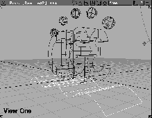
Reset view. Click on the Top, Front, Right and Perspective windows to reset them to defaults.
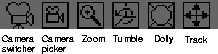
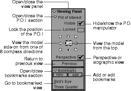
While the Cameras tools are useful, you must interrupt other tool and menu choices to use them. To enable a faster workflow, you can use either the camera tool icons or the Viewing Panel.
The camera tool icons, shown below, are located in the window title bar. Click-drag on the icon to change the view without disturbing the current menu function.
The Viewing Panel enables you to quickly move the camera to preset locations. To display the Viewing Panel, press the Alt and Shift keys.
To move the camera, use the following hot key combinations:
Alt/Shift & left mouse button for Tumble.
Alt/Shift & middle mouse button for Track.
Alt/Shift & right mouse button for Dolly.
| Note: For more information, see What's New in Alias and Modeling Window Control Icons in An Introduction to Alias in the Alias Overview Book. |
| Note: With the view icons, you must drag on the icon. This is different from the Camera tools, where you drag in the window. |
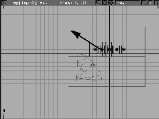
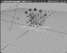
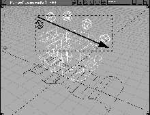
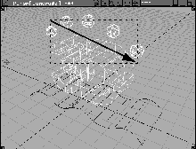
Alt/Shift keys and drag in the Perspective window with the right mouse button to Dolly the view until the scene looks like the following:
Throughout the Learning Alias lessons, you will constantly need to change views to work properly with the geometry. You should become familiar with these icons and the Camera tools in order to perform view changes when they are needed.
A basic skill that you must learn is the ability to pick one or more objects to make them active. This helps you establish which object you want to work with at any given time. Alias includes various Pick tools that offer you a number of picking options.
Object Types All obj/lights. Now all the objects and lights in the scene are picked. They are highlighted to show they are active.
Nothing. This unpicks all the objects and lights.
Object. Click on one of the wire lines belonging to one of the spheres to pick it. It becomes highlighted.
Object still selected, click on the wire lines of two more spheres. They now are highlighted and added to the selection set.
Object still selected, click again on one of the picked spheres with the left mouse button. It is now unpicked or deselected.
Object still selected, click on a different sphere with the middle mouse button. Object still selected, click- drag with the left mouse button to create a pick box around the five spheres and the 3D text. The picked sphere is unpicked, while the other objects are picked.
This is because the middle button replaces the old selection, while the left mouse button toggles it.
|
Tip: Using the middle mouse button to click in empty space is the same as a Pick Nothing without leaving the Pick Object tool. |
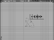
Object. Click on either the number or the letter of the 3D text. The text has been grouped into a single object, and as a result, picked as one.
Nothing.
Component. Now click on one of the wire lines that belong to the front face of the number 3. Only the chosen surface is picked, since it is a component of that text group.
Nothing.
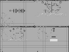
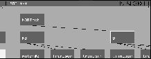
Sometimes the modeling windows contain too much visual information and it is hard to discern one object from another. The Scene Block Diagram (or SBD window) offers a graphical inventory of your objects and their hierarchical relationship. Use the SBD window often to supplement the work being done in the modeling windows.
The Advanced SBD window (or ASBD window) offers additional methods of organizing the various elements of a model. The ASBD uses drag functionality for grouping and arranging the inventory of objects, and for the ability to break larger models onto parts that are placed on separate pages. The ASBD window will be used in a later lesson.
Object selected, click on the 3D text in the modeling window.
The 3D Text is represented by several icons known as dag nodes (Directed Acyclic Graph). The brown nodes represent the positioning, scaling and rotational information about an object. The blue node represents the actual surface geometry. Usually you will use the upper nodes to work with objects, but occasionally you will need to work with the lower nodes.
In the case of the text, there are three levels to the hierarchy. The top node represents the whole string of text, while the middle node represents the two letters separately. The lower brown nodes represent the positions of the surfaces that make up the text, while the blue nodes represent the actual geometry.
 . This moves the position of the DAG node in the SBD window.
Object still selected, click-drag a pick box around two of the sphere nodes with the left mouse button. In the modeling views, the spheres and the 3D text are now picked.
. This moves the position of the DAG node in the SBD window.
Object still selected, click-drag a pick box around two of the sphere nodes with the left mouse button. In the modeling views, the spheres and the 3D text are now picked.
| Tip: Many of the same rules that apply for picking objects in the modeling views apply to picking in the SBD view. |
Object still selected, click on the node named D with the middle mouse button to pick it alone. In the Perspective window you see that you've picked the letter D separately from the number N3.
|
Tip: Sometimes you want to work with the pieces of a dag. You can do this in the SBD window using Pick Object or in the modeling views with Pick Component. |
Object still selected, click on the top node of the text. Since an upper and a lower dag node cannot be picked at the same time, D is unpicked in favor of the N3DText node.
Object selected, click in open space with the middle mouse button to pick nothing.
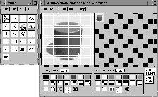
The models are currently being displayed as wireframes. Although wireframe models give you visual information about the shape of an object, the wire lines may not let you edit the parts of those objects or see the shapes as they react to light. Alias has various Display options to give you greater control.
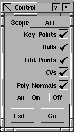
. In the Control window, set the Scope to ALL and click the All On button.
Click Go. Now all the objects in the scene display Key Points, Hulls, Edit Points, CVs, and Poly Normals. You will learn what these controls are in upcoming lessons as you use them to edit the surfaces of objects.
All Off then click Go. The controls have now been turned off.
Under Scope, you can set the controls for New Curves, Surfaces and Polygons. The default settings give you controls where they are needed but you will often need to change these settings during a project, depending on how you work.
Control Window.
| Note: In the Shade option box, you can choose to shade only one view window at a time or only the active object. Together, the speed of your machine and the amount of geometry in your model will determine whether or not Shade should be used. |
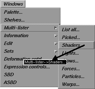
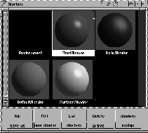
The Multi-lister is where shaders and lights are displayed. You will learn about this powerful feature in a later lesson. For now, you can open it and view the shaders and lights as they are shown in this window.
Shaders... to open the Multi-lister.
Shaders are visual representations of material attributes that can be assigned to objects in your scene. Shaders for this model have already been created for all the different pieces of the scene. These shaders will be applied to your objects when the scene is rendered. You will learn more about shaders in upcoming lessons of this book.
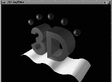
Pix. In the File lister, click on the file named L01_RayTrace and click on the Show button.
The image is a final RayTraced image of the scene that combines the geometry, lights and shaders. You will learn more about rendering in upcoming lessons.
menu icon at the upper left of the window and select Quit. You can also click on the image to close it.
You have now seen the basics of the Alias User Interface. You will now learn how to exit from Alias.
Yes to the prompt Do you really want to quit?.
| Note: If you had wanted to keep the file, you would have needed to save it. You will learn how to do this in the next lesson. |
You have now completed your first lesson. In this lesson you have learned how to: