RetainWall provides reinforced concrete design based on American Concrete Institute's ACI
318 code. The following steps are required to design the reinforced concrete.
1. Specify the unit weight (including reinforcement for reinforced concrete wall), compressive
stress (f'c), elasticity modulus (E) and Poisson's ratio (m) of the concrete, as well as yield
stress (fy), elasticity modulus (E) and concrete cover thickness of the reinforcement
through Material properties window. 2. Open the Reinforced concrete design window through Calculate > Concrete design menu,
Concrete button or  toolbar.
The following window will be shown.
toolbar.
The following window will be shown.
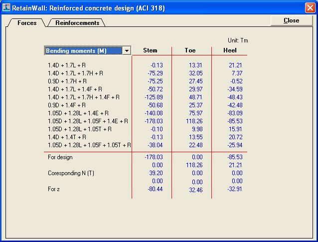
Forces tab and Bending moment (M) selection box with factored bending moments of the
stem, toe and heel for all load combinations are shown, including the design moments,
corresponding normal forces and unfactored moments for z. For the stem, positive values
are for counterclockwise and negative values for clockwise. For the toe, positive values
are for clockwise and negative values for counterclockwise. For the heel, positive values
are for clockwise and negative values for counterclockwise.
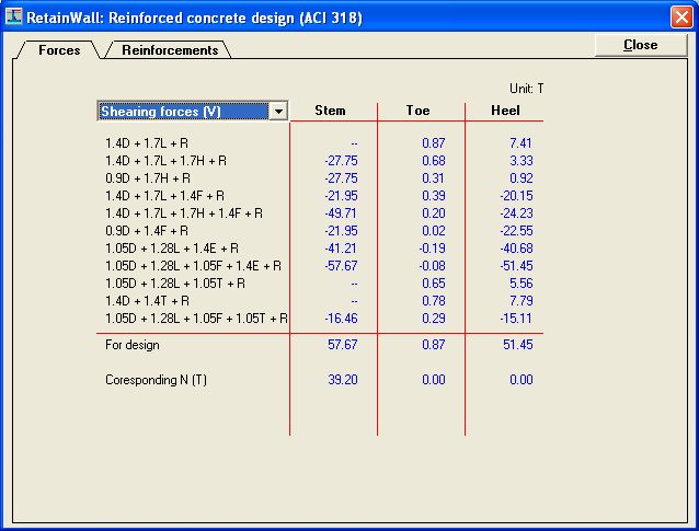
Click the selection box to change the view to Shearing force (V). The following view will
be shown.
Factored shearing forces of the stem, toe and heel for all load combinations are shown,
including the design forces and the corresponding normal forces. For the stem, positive
values for rightward and negative values for leftward. For the toe, positive values for
upward and negative values for downward. For heel, positive values for downward and
negative values for upward.
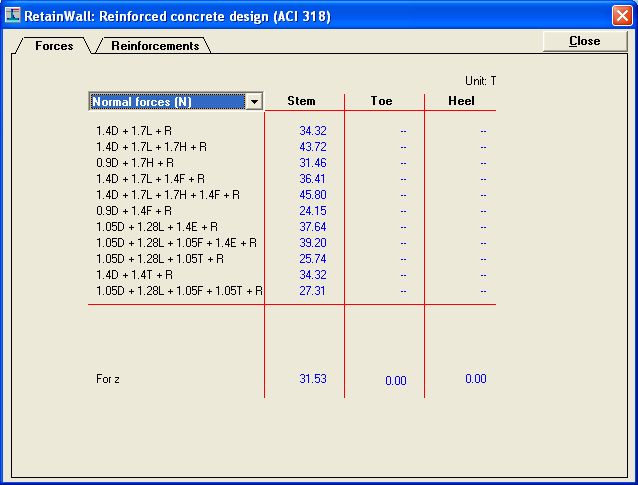
Click the selection box to change the view to Normal force (N). The following view will be
shown.
Factored normal forces of the stem for all load combinations are shown, including the
unfactored force for z. Positive values for compression and negative values for tension.
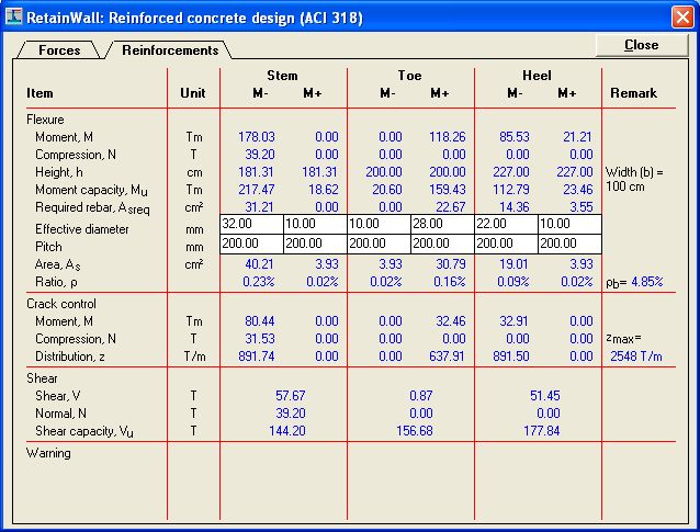
3. Click the Reinforcement tab. The following view will be shown.
Flexure, crack control and shear design parameters are shown for the stem, toe and heel.
Specify the effective diameters and pitches for the positive and negative moments. If the
effective diameters and pitches are not satisfactory according to the code, warnings will
be shown and the diameters or pitches shall be changed.
4. Click  button, "Enter" or "Esc" keyboard key to close the window.
See also: