General
The reinforced concrete is designed with the strength design method in accordance with the
American Concrete Institute Building Code ACI 318. This section described important
requirements and methods stated in the code. The whole requirements and methods are
referred to the code.
Strength reduction factor
The design strength of a reinforced concrete is taken as the nominal strength multiplied by a
strength reduction factor. The following table shows the strength reduction factors (f) for each
type of force and load.
a. Flexure, without axial load 0.90
b. Axial load, and axial load with flexure
• Axial tension and axial tension with flexure 0.90
• Axial compression, and axial compression with flexure
for member with spiral reinforcement 0.75
for other reinforced member 0.70
See the ACI Code for equations to increase the above values.
c. Shear and torsion 0.85
d. Bearing on concrete 0.70
Reinforcement cover
The following table shows the minimum concrete protection for reinforcement of cast in place
concrete (non prestressed).
Condition Minimum
cover (mm)
a. Cast against and exposed to earth 70
b. Exposed to earth or weather
#20 through #55 bars 50
#15 bar, W31 or D31 wire, and smaller 40
c. Not exposed to weather or ground
- Slabs, walls, joists
#45 and #55 bars 40
#35 bar and smaller 20
- Beams, columns
Primary reinforcement, ties, stirrups, spiral 40
- Shells, folded plate members
#20 bar and larger 20
#15 bar, W31 or D31 wire, and smaller 15
Load combinations
The reinforced concrete members are design to have design strengths at least equal to the
required strength (U) as follows.
U = 1.4D + 1.7L
U = 1.4D + 1.7L + 1.7H
U = 0.9D + 1.7H
U = 1.4D + 1.7L + 1.4F
U = 1.4D + 1.7L + 1.7H + 1.4F
U = 0.9D + 1.4F
U = 0.75(1.4D + 1.7L + 1.7x1.1E)
U = 0.75(1.4D + 1.4F + 1.7x1.1E)
U = 0.75(1.4D + 1.4T +1.7W)
U = 1.4D + 1.4T
U = 0.75(1.4D + 1.7L + 1.4F + 1.4T)
U = 0.75(1.4D + 1.7L +1.7W)
U = 0.9D + 1.3W
where:
D = dead loads,
L = live loads,
H = loads due to weight and pressure of soil,
F = loads due to weight and pressure of fluids,
T = structural or impact loads,
E = load effects of earthquake, and
W = wind load.
Strength analysis
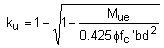
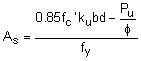
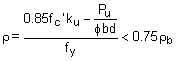
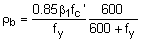
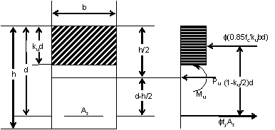
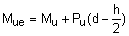
a. Flexure
 ,
, 
 ,
, 
b. Shear
For members subject to shear and flexure only:
For members subject to axial compression:
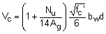
For members subject to significant axial tension:
- shear reinforcement shall be provided to carry all shear.
-  for shear reinforcement perpendicular to axis of member.
 Where:
Mu = factored
moment at section, kNm
Vu = factored
shear force at section, kN
Pu = factored
axial compression load at given eccentricity, kN
d = distance from extreme compression fiber to centroid of tension reinforcement, mm
h = overall thickness of member, mm
bw = web
width, mm
As = area
of tension reinforcement, mm2
Av = area
of shear reinforcement within a distance s, mm2
Ag = gross
area of section, mm2
fy = specific yield strength of reinforcement, MPa
fc’ = specific compressive strength of concrete, MPa
Minimum reinforcement
Minimum reinforcement of flexural members are as follows.
a.  where rmin = minimum ratio of tension reinforcement, fy = compressive strength
of concrete in MPa, or
where rmin = minimum ratio of tension reinforcement, fy = compressive strength
of concrete in MPa, or b. area of reinforcement provided at every section, positive or negative, at least one-third
greater than that required by analysis.
Minimum shear reinforcement requirement can be seen in ACI 318 Code.
Distribution of flexural reinforcement
If fy > 300 MPa,  shall not exceed 30 MN/m for interior exposure and 25 MN/m for
exterior exposure,
shall not exceed 30 MN/m for interior exposure and 25 MN/m for
exterior exposure, where,
fs = moment
divided by the product of steel area and internal moment arm (MPa)
dc = thickness
of concrete cover measured from extreme tension fiber to center of bar
located closest whereto, mm
A = effective tension area of concrete surrounding the flexural tension reinforcement and
having the same centroid as that reinforcement, divided by the number of bars, mm2
 for
for ,
,  for
for