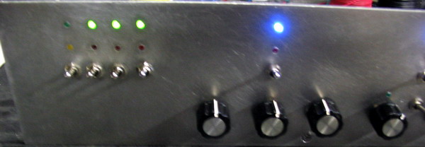
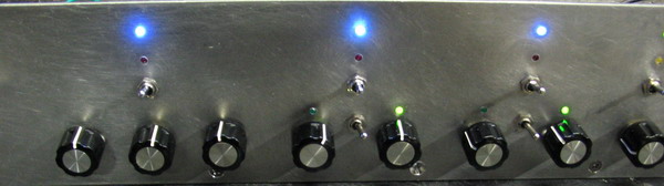
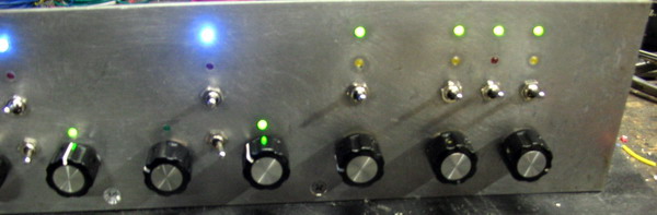
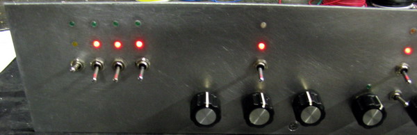
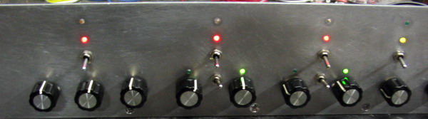
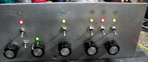
Left, middle and right hand side views. There are two sets of photos; one with all switches in the "up" position, and the second with them all down.
red=off/stop
yel=hold
grn=on/go
blue=active/adjust

| Preselector The Wiring Phase | Home Back Next | |||||||||||||||||||||||||||||||||||
|
||||||||||||||||||||||||||||||||||||
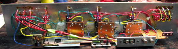
| Here is a view of the wiring as I just finished - the solder is barely cool! Note that I have not done much in the way of dressing the wires yet. To help with future modifications, the wiring color scheme is: red= +12 volts, black (or bare)=ground/common, green=signal path, yellow=signal input (to filters), blue=signal output (from filters). | ||||||||||||||||||||||||||||||||||||
|
||||||||||||||||||||||||||||||||||||
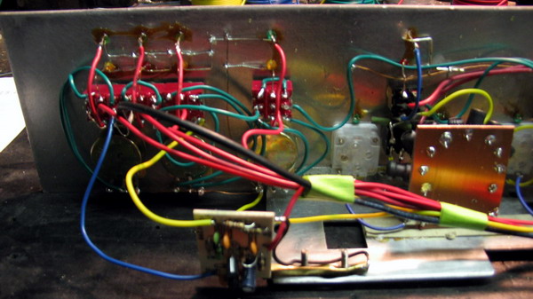
| Wiring detail of the preamp control circuit. The amplifier is the small PC board at the bottom-center (yel=input, blue=output). Note that the output wire is kept physically seperated from the input to avoid oscillation. The white square in the center is one of the plastic (not air) variable capacitors. Note that without the LED status indicator lights, the wiring of this unit would be less-than half of what you see. It's a pain, but I tend to listen in a darkened room and the lights make adjustments almost intuitive - plus they are sexy! | ||||||||||||||||||||||||||||||||||||
|
||||||||||||||||||||||||||||||||||||
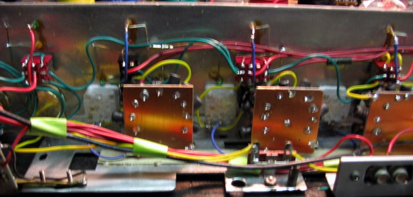
| Here's a closeup of the mid-section. The square PC boards (3), are drilled in a circle which corresponds to the rotary switch contacts. This makes mounting the inductors nice and neat, with short and direct leads. | ||||||||||||||||||||||||||||||||||||
|
||||||||||||||||||||||||||||||||||||
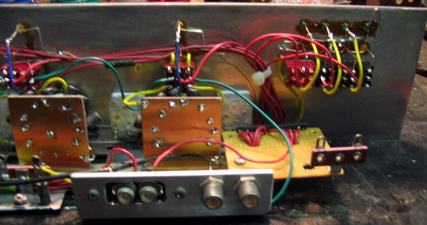
| This is the input side (left-front). I used dual RCA phono jacks for the 12 V feed. One jack for the power and the other for loop-thru to power other accessories. The yellow vector board with the 2-lug terminal strip, and the red wire bundles, contains the 2.2K Ohm SIP resistors, which feed the LEDs at about 6 mA each - that's bright enough. The signal input and output is via the two "F" connectors. | ||||||||||||||||||||||||||||||||||||
|
||||||||||||||||||||||||||||||||||||
| These next six pics are just a "show-and-tell". Left, middle and right hand side views. There are two sets of photos; one with all switches in the "up" position, and the second with them all down. |
||||||||||||||||||||||||||||||||||||
| Remember the standard color scheme: red=off/stop yel=hold grn=on/go blue=active/adjust |
||||||||||||||||||||||||||||||||||||
|
||||||||||||||||||||||||||||||||||||
|
||||||||||||||||||||||||||||||||||||
| The next phase is to sit at the computer and print the face decal. It will be similar to the blue and grey one on the previous page. | ||||||||||||||||||||||||||||||||||||
|
||||||||||||||||||||||||||||||||||||
|
||||||||||||||||||||||||||||||||||||
|
||||||||||||||||||||||||||||||||||||
|
|
||||||||||||||||||||||||||||||||||||
| Added: Presidents' Day, 2-20-06 | ||||||||||||||||||||||||||||||||||||