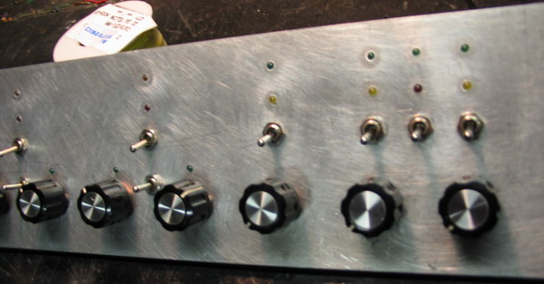
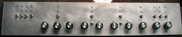
4 toggles = panel function, mode, etc. w/status indicators.
3 knobs = Pi network tuner (matcher) w/ bypass switch and indicators.
2 knobs = resonant peaking circuit (bandpass) with mode and function switches and indicators.
2 knobs = resonant nulling circuit (bandstop) with (ditto, above).
1 knob = attenuator w/ bypass and status LEDs.
2 knobs = And 3 toggles control preamp mode, function, sensitivity, and gain, plus status lights.
* * * See schematic (here) for mode, function details * * *
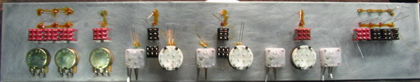
1. LEDs are tight press fit in panel (0.110" - 0.114") and contact cemented for safety.
2. The 4 variable caps are of the transistor portable radio variety (22 - 224pF) with polyethylene dielectric instead of air, but there is enough room for the real thing which normally are 14 - 365 pF.
3. All 3 pots are 5K Ohms linear.
Note that if you are not as OCD as me, you could eliminate the status indicator LEDs and not have to buy the more expensive 3PDT switches, since the whole thing can be built with DPDT and SPDT switches - it's your call. The design philosophy here is: I'd rather disassemble a Cadillac to make a Chevy, than try to do the reverse.

This page updated: Jan 28, 2006