 |
|
|
|
|
|
|
|
|
|
|
|
|
|
|
|
|
|
|
|
|
|
|
|
|
|
|
Preselector The Testing Phase |
|
|
|
Previous
Next
Home |
|
|
|
|
|
 |
|
|
|
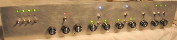
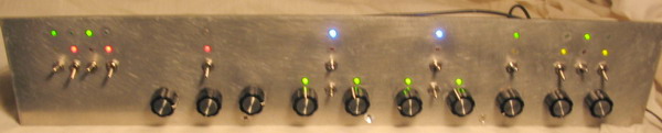
Here's a couple of shots of the finalized layout before the front (nomenclature) decal gets stuck on. All controls and indicators are layed out on a 1/4" grid to make use of the graphics program more precisely. |
|
|
|
 |
|
|
|
Before generating the plastic decal, I wanted to finalize any last-minut changes. The first 4 switches are: power, antenna/shunt, system operate/standby, and system bypass, respectively. The first 3 knobs are for a Pi network tuner (to establish a good impedance match for the preselector, the next 2 knobs are the bandpass filter with "L" and "C" controls (the switch between the knobs selects L, C, or L+C as indicated by the green indicators), likewise the next 2 knobs are the band-stop filters. Third from the right is the overall system attenuator, followed by the RF Preamp with an input sensitivity control and an output gain pot. Note that all functions may be switched out of the circuit with the switches above the knobs and LEDs which indicate their mode. The reason for this added complexity is to allow a "set-and-forget" convenience of the controls - when not needed, or wanted, the control can be switched out of the circuit without changing its setting. |
|
|
|
 |
|
|
|
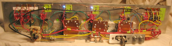
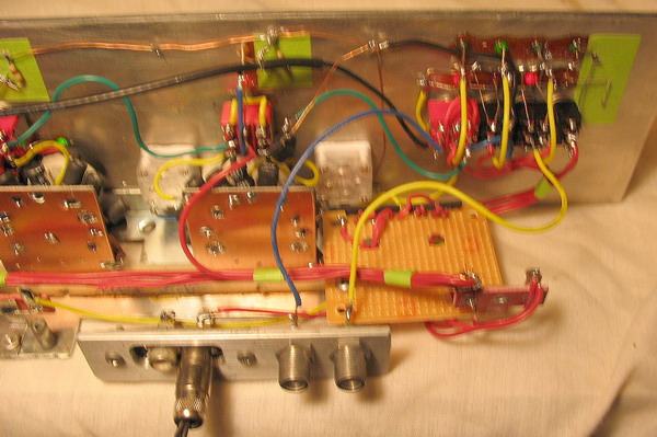
The wiring completed. Note that only the (high gain) outputs are wired with shielded cable (RG-174 coax). Eventually a sheet metal enclosure will be fabricated to shield the entire assembly.
Wiring code: Red wire = power, yellow = signal returns, green = signal path, black = grounds. |
|
|
|
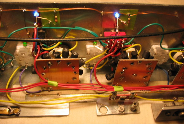
Closeup details. The assembly of the inductors to the 12-position switches were wired as three seperate modules. The power, signal, and ground wires are harnesses and routed away from one another, since there is 18-20 dB of RF gain available and oscillation is easy to come by.
Note the redundant ground bus running along the top of the panel above the LEDs, to avoid ground loops.
I spent several hours testing this thing last night - it's amazing what capabilities a receiver has when fed a healthy diet!
Chances are, you never really heard your radio, at its best! |
|
|
|
 |
|
|
|
|
|
 |
|
|
|
This is typical of the control wiring. Since they never seem to fail, the LEDs are cemented into the front panel. They now run at between 6 and 12 mA, depending on the color and the brightness needed.
The wires with service loops are there to allow removal of the sub-chassis for mods, servicing, etc. |
|
|
|
|
|
Click above to go to the next page and see the front panel labeling. |
|
|
|
|
|
I may begin printing the front decal this week ... it is now 10:00 AM, Sunday, February 26, 2006, and I have domestic engineering to do...NOW! |
|
|
|

|
|
|
|