The VK4YE 1 Kilowatt Linear Amplifier.
Back to the main amateur radio page
Description.
The amplifier described in this article works satisfactorily with plate voltages ranging from 1.5kV to 2.5kV and easily exceeds 400W pep output from 160m to 10m. If you are inexperienced with, or hesitant about working with high voltages, forget about tackling this project. There is no such thing as a "slight shock" from a 2.5kV power supply. IT IS LETHAL!
Turning to the circuit in Figure 1, drive is applied through contacts RA1 of input relay RA. I have separate input and output switching relays. Relay RB has the antenna change-over function. These two relays pull in together when a relay in your rig closes after the press to talk button is pressed. You must ensure that this relay has a set of contacts which places an earth on the "ground side" of RA. If you are unsure, read your manual. The 1:4 unbalanced to unbalanced [ unun ] transmission line transformer transforms the 50 ohm impedance to 200 ohm to match the 200 ohm grid resistor, which should be rated at 20W. I used a commercial 200 ohm 50W non inductive resistor. Surprisingly, 5 x 1k ohm 5W resistors in parallel gave quite satisfactory results, particularly as they have some inductance.
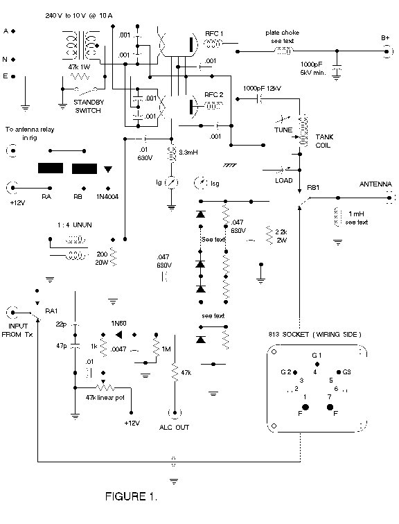
Drive is sampled and fed through a 0.047mF 630V capacitor to the rectifier-doubler which comprises 12 BAW62 diodes, each shunted by a 220k ohm 0.5W resistor. There are 6 diodes in each leg. A DC voltage proportional to the driving signal is applied to the screen grid of each 813. This method of generating the screen voltage works extremely well. The tubes draw around 40 - 50mA of plate current with no drive, as the screen voltage is zero. With drive, the screen voltage rises quickly to 200V or so. Do make provision to meter the screen current as it is a better indicator of resonance in the tank circuit of tetrode and pentode tubes than the conventional method of dipping the plate current.
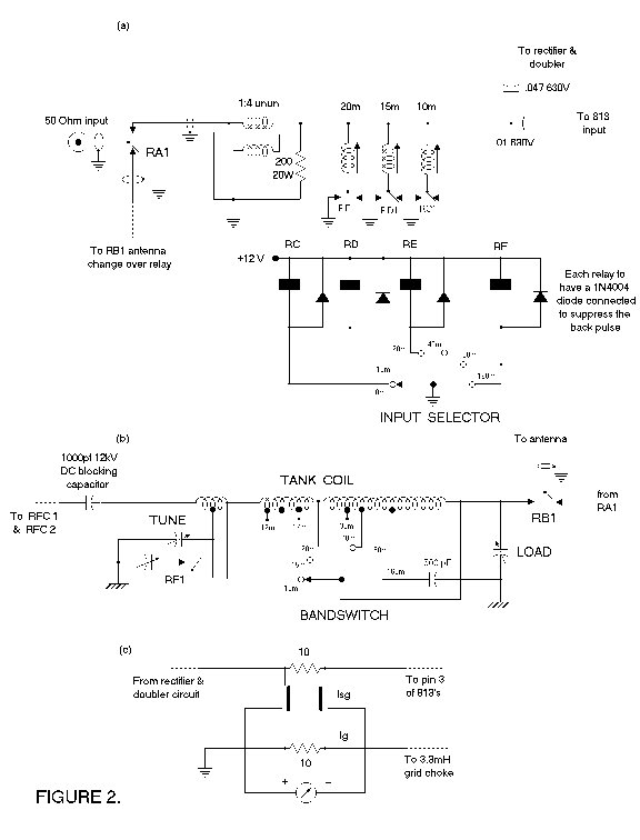
A 0.01mF 630V capacitor passes drive to the control grid of the paralleled tubes which are operated in zero bias class AB2 configuration. When driven positive, grid current flows through a 3.3mH RFC [ Altronics L 7052 ] and must be metered with a 100mA FSD meter as it indicates the level of drive from your rig. While separate meters are shown to read Isg and Ig, you may use one meter. A DPDT switch is used in my amplifier. 10 ohm 0.5W resistors bridge the position nominally occupied by the meter to complete the circuit when the meter is switched to the other position. See Figure 2 (c) for a circuit of this arrangement.
You will notice that on the circuit diagram in Figure 1, I have a different symbol for earth at the grounded end of the plate and load capacitors. All connections made to this point, like the beam forming plates and the filament and screen bypass capacitors should be connected by 1 cm wide copper strap or brass shim. Because the tubes are not neutralised, it is imperative that a low impedance common ground be available to prevent instability. No trace of errant behaviour has been detected in the two amplifiers made to this design.
The 1mH RFC across the output is a mandatory safety item. Should the 1000pF DC blocking capacitor ever break down, you will have the high tension supply connected to the antenna system. The choke will shunt the DC to earth and open the 10A fuses in the primary side of the plate transformers. Under no circumstances is this choke to be left out. It comprises at least 100 turns of 0.4mm enamelled wire on a 50mm length of ferrite rod. Apply a layer of insulation tape before and after the winding is done. It does not matter if 2 or 3 layers of wire are used. Antenna change-over relay RB is an Altronics S 4197 job.
Back to the projects main page.
Click here
Home |
About Us |
Amateur Radio |
Bikes |
Blacksmithing |
Books |
Downloads
ICQ Me |
Site Info |
Links |
The Loaded Dog
Get your Free Email account here!
Sign Guestbook | View Guestbook
A web page is only as good as its weakest link. If you find a dead link please e-mail me at [email protected]
All information contained on these pages is copyright ©. Please ask the respective author if you want to reproduce anything.