1A01515: BANDPASS FILTER DESIGN
Currently, the area density of magnetic data storage technology is increasing at an annual rate of 80-120%. Finding the height between the read/write head and the disk plates becomes more critical, with an expected increase of area density to 200Gb/in2 and decrease of the flying height between the head and the disk from currently 25nm to a possible of 10-12nm.
There are different methods of finding the flying height between the read/write head and the surface of the disk plate. DSI (Data Storage Institute) has developed a method called the triple harmonics method to calculate the flying height between the read/write head and the surface of the disk plate.
For this method, the amplitudes of the modulating signal of the read back signal and its harmonics are required. These read back signals that are in the form of AM signals. It has a modulating signal of 1kHz - 200kHz, modulated by a carrier signal equivalent to the test frequencies. When carrying out signal testing, in order to pick out the test signals within different bands, a large number of band-pass filters/demodulators with the corresponding central frequencies will have to be designed. This makes the job tedious, impractical and a waste of resources.
The objective of this project was to build a tunable demodulator that is able to demodulate an input read back signal of any frequency within the bandwidth of 10MHz - 400MHz. The expected output of the test board will be the modulating signal.
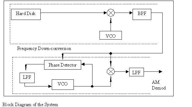
This is done by first down-converting the input read back signal to a fixed
IF of 10MHz by applying the heterodyne theory, before demodulating the signal
using coherent demodulation to obtain the modulating signal.