|
|
| Overview Parts List Installation Printable PDF FAQ |
Installation of
the EWP (continued)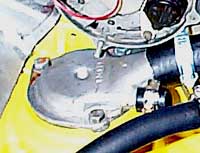 Step 7. Installing the waterpump cover. The waterpump cover is installed using a new gasket. The inlet port on the cover is capped by use of a rubber cap and a hose clamp. |
Step 8. Plumbing the Pump.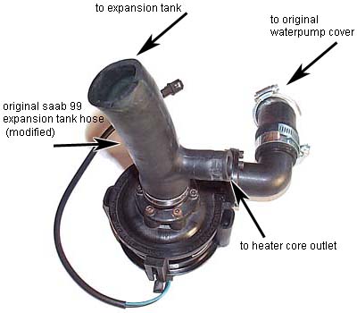 |
This photo shows the EWP configured with an elbow piece on the outlet and a straight piece on the inlet. The elbow and straight pieces come with the EWP. The
original 99 hose from the expansion tank is cut and attached to the
inlet
of
the EWP
and is oriented as
pictured. |
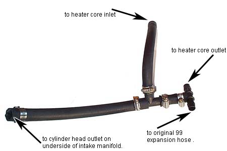
Step 9. Fabricating the Plumbing |
| Next, a section of plumbing is created using an 11 inch piece of 3/4" heater hose, a 9 inch piece of heater hose, and a small 2 inch bypass hose coupled with two plastic 'T' connectors. This section will carry coolant from the cylinder head back to the EWP, allowing some to go through the heater core first. |
|
| Got Questions? email the author |