Adam & Ruth’s
DFE Ascender III-C Builders’ Logbook
This aircraft building logbook is now complete. For follow-on information see the Flight Log
The latest entry is 02 August 2003
19 August 2001 – We both drove down to DFE Ultralights and visited with Dave Froble there on the 19th. On the 20th we each went for a flight in Dave’s Pterodactyl Ascender II+2 (upgraded to a DFE Ascender III-C). Ruth’s reaction as soon as she landed was “I love it – buy one”. On the drive home we discussed the plane and decided to do just that and ordered one. The full story of the evaluation flights is told in Jurassic Flying, our article for Canadian Flight and Pterodactyl Perfection our article for KitPlanes. The total cost for the Ascender III-C is estimated as $15,368.05, plus tax.
22 August 2001 – We ordered our kit via e-mail from Dave Froble. He indicated that the kit would be ready in six to eight weeks and we arranged to drive down and pick it up.
11 Nov 2001 – Dave had said that the kit was as close to complete as it was going to get, so we took a couple of days off, rented a van and drove down. The trip was long – 13 hours down and 12 back, but the border crossings were no trouble. We loaded the kit and paid Dave on the evening of the 11th, some 81 days after we ordered the kit. The kit wasn’t complete as Dave admitted that the stub axles, sidecar front and centre struts and canard leading edge were still backordered. The RH throttle is also missing, as Dave needs to develop it, as he has promised to do. Dave did ask us if we would like to stay an extra day down there to do an inventory, but we declined. That may have been a mistake, as checking the kit list on the way home indicated that there were some obvious items missing from the lists – like the control stick. Before packing we asked Dave about a few items and he admitted that the rib and wing bags weren’t on the list, so he threw those in the box. Dave has promised to ship us anything missing, of course. We trust him, as he isn’t doing this professionally it makes it less of a desperate enterprise. The next big job for us is an inventory of what we got and what we are missing.
Photos:
Going to get the kit at the Dac farm
The whole Pterodactyl fits in a rented van with room to spare
On the road home with our plane Ruth is excited
18 Nov 2001 – Inventory Day – This was interesting! It took the two of us about an hour and a half to inventory all the parts. It looks like pretty much everything on the parts lists is actually here. We also got 31 parts that weren’t on any lists. That’s a good thing because they are needed! This included the control stick and grip, for example. Obviously we are going to provide this list to Dave so he can update his lists for future kits. Then there is the third group – the items that we didn’t get that aren’t on the list. This group is very hard to define since we don’t know what is missing, but unlisted. So far we have identified a few things that are on this list – like the tires. So the next phase was to send Dave a report on what we found. That task was completed via e-mail today. Now we’ll wait to hear from Dave. The missing parts are kind of a drag as they include some critical items that will make it hard to get started. The canard is the usual first item to start with, but without the leading edge that is rather difficult. The next task is to read the builder’s manual. The first run through it reveals that while it has some nice photos it doesn’t have any detail in some areas. I can see that we’ll have to make up for that with photos and e-mail to Dave. Building time today was 3.0 hours. Total = 3.0 hours
20 Nov 2001 – We bought the tires and tubes and decided to try mounting them on the rims. It went reasonably smoothly and only needed one kitchen spoon (one of the bigger ones) We then pumped air into all three wheels and were deliriously happy. Building time today was 1.0 hour. Total = 4.0 hours
Photos:
Sign of the times at our house
Can you actually build an airplane in your living room?
The main wheels are very decorative
30 Nov 2001 – After talking to our local Rotax dealer, Daniel Sasseville of Aero Propulsion Technologie of St Lazare we have settled on an engine package and have ordered it today. It will be a DCDI 503 with two carburetors. We are also ordering our engine instruments from Daniel. We will get a CHT, EGT, tach and Hobbs meter. These we are planning to mount in a removable pod instrument panel from Aircraft Spruce. Daniel says all the parts should all be in the week after next. We will then drive the 1.5 hrs down to St Lazare to get them. The 50 hp Rotax 503 will leave the Ascender with lots of power, as the power loading at gross weight of 750 lbs will be 15 lb/hp, which is comparable to a C-172P. At normal operating weights of 620 lbs the power loading will be 12.4 lb/hp, which is about the same as a C-182K. It should climb very well with that kind of power.
02 Dec 2001 – We spent some time thinking about the dual throttle arrangement, which Dave said he’d have to put some design work into. After some drawings and then looking at some old photos from 1982 we think that the original design is probably the best idea. This will only require fabricating two new throttle levers – an easy job as they are just made from thick sheet and involve no bends. We drew up a new LH throttle design and will use the existing throttle for the RH one. We have asked Dave whether he will make the new throttle levers or we will. Still waiting to hear on that. We have noticed that when we send a list of questions to Dave he usually just answers one and the rest get missed. It means that we are having to ask just one question at a time and save them up to ask him. I have asked him several times about when we can expect the missing parts – no answer on that at all. I am becoming increasingly concerned that we won’t be flying in the spring at this rate.
03 December 2001 – We worked on the nose wheel assembly but managed to get it to at least look okay. The reason we wanted to tackle the steerable nose gear was that it was the one part of the aircraft that had no instructions with it at all (horrors!). This is because the builder’s manual is still the stock Pterodactyl manual but the SNG was designed and then added later without any changes to the manual itself. This is obviously a drawback and at least an exploded parts view would be a great help. The gear itself is shipped with the forks mounted upside down to make for a smaller package but it does mean that you have to disassemble most of the gear in order to get it right! Between the parts list and the Pterodactyl drawings of the axle, we were able to put it all back together in the correct manner. The nose gear Teflon bearings required some sanding to get a proper fit. Other problem areas were the SNG main carrier cross tube which has a difficult plastic fitting that is bolted in place. We nearly resorted to gluing it but finally got the two bolts home okay. The SNG front cable housing does not fit through the front axle with the bolts in place, so fitting the front landing gear cables is going to be very interesting. The rotator rod sleeve to the main carrier and main carrier cross tube have recessed heads which made tightening the nuts very difficult as you cannot get a socket or any other tool on the bolt head. The solution in the end was to use a very small screwdriver blade to wedge the bolt head while tightening the nut. Instructions for the nose gear are definitely required. Building time today was 3.0 hours. Total = 7.0 hours
Photo:
One of the first sub-projects was the DFE steerable nose gear
04 Dec 01 – Today was the day to have a kick at the control stick assembly. The parts are beautifully made with only a few adjustments needed to get a good fit on the pre-drilled holes. Assembly today went okay with a few notable exceptions. The Pterodactyl manual has a control stick design. Dave has inserted a sketch of a “modified design”. On top of that he has a “new modified design” that he has installed on his III-C at home. I think that we have the parts to make the Mark II design, which seems to have been designed to lower the stick for comfort. Construction went okay – it was nice to actually do some drilling and riveting again and to use my collection of clecoes! They worked as well as always – the builder’s most indispensable tools! The disappointing part was discovering that between the confusion over the three styles of sticks that we are missing pieces. These are the Control Stick post cap, which is not important and two bolts, which are. Once again I am going to have to drop Dave another note about this. I am hoping that this will be the end of the parts problems and the big questions as the rest of the plane is stock Pterodactyl and therefore basically follows the manual – hopefully. Building time today was 2.0 hours. Total = 9.0 hours.
Photo:
06 December 2001 – Tonight I decided to inventory the P000-811 Full Hardware Kit – Ascender III-C/II+ that came with the aircraft kit itself. This involved just sitting down at the computer and typing each plastic bag contents into the Word document. Then for good measure I updated and simplified the other two lists that I have going – The List of parts we found that weren’t on any packing lists and the List of missing parts. I sent that last list to Dave for some answers. I also sent him an apology for getting some part numbers wrong the last time I sent him the list. I am getting a bit concerned as he hasn’t let us know when we are going to be getting the missing parts. We are beginning to get stymied by the missing parts, as we can’t finish much without them. So far there are none that are real showstoppers as we can make them all if we have to. Even the three missing tubes are all non-bent ones, so that shouldn’t be a big deal, if we can get the specs for them. I did ask him for an answer to the specific questions we had. I hope he gives us a date to get all this stuff soon. I would love to have had the canard done by now, if only we had the leading edge. Building time today was 1.5 hours. Total = 10.5 hours.
08 December 2001 – Today I started in on a couple more sub-assemblies. This time I tackled the canard mounting clevis tubes and the canard pushrod. Both involved drilling a few holes and setting some rivets – always pleasant work. Both went fine and took about an hour, with all the de-burring and test fitting. I like to work slowly and carefully, especially when rivets are involved. It saves drilling them out and starting again. The solid rivets on the clevises went fine, using the anvil and ball-peen hammer. I was pleasantly surprised how easily they set. I finally ran out of parts, however. It was the SS 1/8-inch pop rivets that were the first to go. The kit came with 8, which is about 20 short of the number needed. Fortunately I had some in stock from the Lazairs.
Photos:
We are almost at a crisis point with the kit. Today the two of us went through the instructions and counted out bolts. As suspected we have nowhere near the number required in the sizes required. On the other hand we have several sizes that we can find no mention of at all. Are these substitutions? We have no way of knowing. Because of the missing parts we are close to having to stop work on the plane altogether. This is not impressive. It is very apparent that there is no master list of parts for the kit and that our kit was thrown together from “a bit of this, bit of that”. The end result is as described – lots of missing parts. So far Dave has not been responsive to my questions about missing parts at all. I now have a lot more parts to catalogue as missing and not much hope that I am done with that list. Certainly as we try to do more sub-assemblies we’ll find more missing parts and get stuck, unable to proceed. This is getting very frustrating.
Building time today was 1.5 hours. Total = 12.0 hours.
09 December 2001 – Today I managed to put a few subassemblies together without running out of parts, but it is getting more difficult as time goes by. The parts we have are beautifully made and generally fit well with few adjustments. Tonight I took an hour and put together the main axles. They are solid and heavy and look like they will well do the job. As usual, they are nothing like the original design, they are a good improvement. This of course, means that the diagrams in the original Pterodactyl Builder’s manual show something totally different. It wasn’t a problem in this case, but the manual needs totally replacing to be effective. It is obvious that Dave has put a lot of thought into the new parts he has designed, but they need new documentation to be a complete kit plane. I am very thankful that we took lots of 35mm and digital photos of Dave’s plane, or else we would be at a loss as to how the thing goes together.
Photos:
Axles are fitted to the main wheels
After the main gear I also finished off assembling the canard mounting tubes by adding the hardware that will go with them. The last project tonight was working on the main axle itself. Another beautifully designed piece of gear the three concentric tubes fit together fine. I would have installed the adaptors, but the correct orientation requires that the hang tube frame be completed first. That will be the next project. Building time today was 1.0 hour. Total = 13.0 hours.
21 December 2001 – Today we drove out to visit Daniel Sasseville of Aero Propulsion Technologies at the St Lazare Airport. The drive took about 1.5 hours each way, but was very pleasant in the new snow. The world looked very wintry and quite sunny. Daniel was his usual helpful self and had us loaded up with our new Rotax 503 DCDI engine and accessories fairly quickly. We’ll have to unpack the engine and instruments and have a look at everything, get it ready for installation. That will include reading all the manuals that come with the engine – Installation, Operators and Maintenance.
Photos:
We took delivery of our very own Rotax 503 engine
The engine comes with a nice little Rotax tool kit too!
The engine spent a lot of time in our living room during the building
Our cat Zuby was curious about the engine
And then
adopted it as her very own perch
27 December 2001 – I’ve been very sick with the flu this week. So much for that great flu shot we all got here in Ontario! I guess it was the wrong shot for this year. It has kept me down for a week and greatly delayed work on the Ascender. I did manage to install the new decal package that I ordered from Falcon Design here in Ottawa. The stick-on decals look really nice on the rudders. The Certificate of Registration came through from Transport Canada. I had counted on it taking six months and so applied early for the marks. I guess they didn’t want to cause problems as I was prepared to fly without the C of R, since I had paid for it and let CAT sort it out. No chance of that now as the C of R arrived in record time. I guess it helps to be a troublemaker! Building time today was 0.5 hours. Total = 13.5 hours.
28 December 2001 – The flu lasted a whole six days and really took a lot out of me over Christmas this year. Mostly it detracted from building the plane, too! Today I took a shot at the noseplate assembly – still working on the small subassemblies while the unheated garage is below zero! Ran into another snag today. The noseplate is a beautiful piece of work – nicely made pieces that are really inspiring to look at. The trouble is when assembled the bolts (AN3-24s) are too long by almost ¼ inch. Another mystery. I quick e-mail exchange with Dave shows what I suspected the Teflon glide plates are wrong. They act as spacers as well as protection for the metal parts. The ones I have with the kit are too thin and thus leave the bolts sticking out too far. More process. Dave says he will send the right glide plates next week along with many of the growing list of missing parts. Meanwhile this nice piece of half-completed art sits on the coffee table as a conversation piece. Building time today was 0.3 hours. Total = 13.8 hours.
Photo:
The nose plate assembly is a beautiful piece of sculpture
25 January 2002 – Almost a month has passed here without getting any work on the plane done – the reason – no parts! I had pretty much run into a wall at every turn with parts missing from the original DFE kit. Yesterday a small package arrived from DFE Ultralights with many of the missing parts in it. It even made it through Canada Customs unscathed. They accepted Dave’s letter declaring that duties had been prepaid on the parts since they were missing from the kit.
So I set to it and inventoried what was sent. I got all the bolts, rivets, screws, nuts and fuel line I had asked for. In fact there are only four parts missing at this point – the canard leading edge, two sidecar uprights and the LH throttle assembly. After the inventory I immediately e-mailed Dave to thank him for sending the package and ask about the remaining missing parts – as of this date I am still waiting to hear back.
I had put together this list of missing parts from the Builder’s Manual. Dave queried what I needed some of the parts for – I only had the manual to go by and he had changed some parts for others without changing the manual. That made it pretty hard to figure out just what is needed. In the end we agreed that he would ship what I asked for and that I would return anything unused when the plane was completed, at our cost. That seemed fair.
The missing parts came at just the right time. I am starting a week off work – my Christmas vacation, better late than never. When I originally booked this week my aim was to do airplane building and it looks like that aim will be met. I hope to be able to have daily entries about how the work is coming along, especially since the skiing looks to be pretty poor this week!
On a related note the February issue of KitPlanes was supposed to carry our Pterodactyl article, but it didn’t. This isn’t an unusual occurrence as they have “slipped” articles on us before. Hopefully it will be in the March issue?
28 January 2002 – Monday on my week off and despite demands to get lots of non-airplane related chores done I did get to put in some time building today. This has been a very mild winter, even for Ottawa, which is normally mild compared to Alberta. This year it is mild compared to Vancouver! The psychological result of this is that it feels like spring is here in the last week of January. Instead of feeling snug at home while the snow builds up outside I am feeling that I had better get this plane finished or else we will miss some good open-cockpit flying weather!
Today I inventoried the engine package and moved the engine and accessories into the warmth of the living room. Having just a non-heated garage to work in isn’t much fun, even when the temperatures are this warm outside – it is still around 0C in the garage. The normal procedure therefore is to bring stuff in for a few hours to warm up prior to working on it. It helps that not only does Ruth not object to having airplane parts in the house, but she actually complains if there aren’t aircraft parts in the house. Can’t beat that! Even our cat, Zuby was pleased that the engine was in the living room.
So today I went through the engine parts. It all seems to be there, except the oil supply bottle and line and the prop bolts. I rather suspected that we’d have to get the prop bolts with the prop, as they have to be matched for thickness to the prop hub. The oil supply bottle is interesting- the Rotax manuals seem to imply that you are on your own with that problem, although I have seen some very nice set-ups on 582s in the past. Were they owner-provided? I will be seeing Daniel, our engine distributor, this weekend at Montebello at the Challenger Association Fly-in, so I’ll ask him then, I guess. There were a few pleasant surprises - the 503 actually comes with a neat little tool kit! That is a nice touch, actually.
The engine instruments look good. We have four of them – tach, dual EGT and CHTs and an hour-meter. They are all Westach instruments. We have decided to mount them on a pod set up from Aircraft Spruce. On top of that the plane will have its ASI, and the Piccolo hang glider instrument set of variometer and altimeter, plus grafted on stopwatch. Someplace I am going to have add a compass to make it all legal and smart. The danger is going to be having instruments all over the place – this will take a bit of planning!
Photos:
Engine instruments – the dual CHT
Engine instruments – the dual EGT
Engine instruments – the Hobbs meter to track engine hours
Engine instruments – the Tachometer
Engine instruments mounted on the panel
The other project for today was to finish the noseplate assembly. Now with the right 3/8 inch glide plates the whole thing went together perfectly! I did have to do a bit of drilling on the lower noseplate to fit the flat-bottom brackets that will suspend the hang tubes. This was a bit tricky as the noseplate itself is an odd shape, which precluded clamping it to drill. In the end a freehand drill on the drill press worked fine and it all fits nicely, including a test fit on the keel assembly, which will be tomorrow’s work. The noseplate assembly is a really beautiful work of art; perhaps I’ll just leave it on the coffee table as a conversation piece.
With most of the parts here and able to proceed the work seems to just flow together. The parts are beautifully made and fit well, when you have the right components! Spring is in the air and the desire to have the plane ready to fly is building. Building time today was 1.0 hour. Total = 14.8 hours.
29 January 2002 – Today was the day to work on the keel assembly. This actually went a little more slowly than I had hoped. Again the Builder’s Manual was to blame – it is quite out of date, which is to say that many items have been substituted in the kit, but the book hasn’t been revised to show the changes yet. So there were two e-mails to Dave to ask him about parts. The first was regarding the rear spar bracket saddles. The book called for plastic ones for the 1 5/8” tube. There were none in the kit, just aluminum ones – were they for something else instead? Dave sent a quick reply – he couldn’t get the plastic ones anymore and so substituted the aluminum ones. Fair enough – I amended my version of the manual to show that.
The second question was regarding how to join the two sections of the keel. It comes in a “fore” and “aft” part and a 3/16 inch hole lines up to keep the two parts together. Was it for a bolt or a clevis pin? Were washers required? The book sort of suggested a clevis pin and the kit contained a 3/16” X 1 5/8” pin. Was it for something else? Dave’s answer cleared it up:
Hmmmm......
Looking at part of the manual, I find:
6. Remove the front section of the keel by removing the clevis pin.
Attach the pip pin (AF33) to the 1/16" cable in the front of the keel
with a 1/16" swage (RG8) by running the cable through the swage, through
the ring on the pip pin and back to the swage. Make sure you have
enough slack to remove the pip pin from the 1/4" hole in the keel.
Clamp the swage with the bare end flush with the end of the swage.
It does mention the clevis pin, but for disassembly, not assembly. I
think the original kits were shipped with the keel sections already joined.
Yep. The clevis pin is used for this job. It should be inserted
from
the bottom, with the ring on top. Yeah, everyone says it could fall
out. Well, with the ring on top, it won't contact the sail. It
could
be a bolt, with the head on the bottom. This isn't a structural part,
at least one that gets a load. The noseplate sure isn't moving forward
with the sail on. The cables and such won't let the front section turn.
It's greatest value is during construction, and, well, it just
wouldn't be right not to pin the two pieces together.
Dave
I guess that the original manual had some problems in the first place – it really needs a rewrite now, 20-odd years later.
I spent part of the day doing a bit of a shopping trip, as I had to go out anyway for a doctor’s appointment. The kit isn’t totally complete – even when you get all the parts that you expect from DFE. As mentioned earlier, the tires and tubes are not included – but we have those now. The seat bottoms are not included either. The seats are sewn ballistic nylon with integral straps, but they need a wooden insert to complete them – not included. I was afraid that I might have to buy a 4 X 8 sheet of plywood to get the two small 11” X 10.5” pieces that I needed. Home Depot came to the rescue with their scrap bin! Steve in the Lumber Dept found a piece of OSB that was 12” X 6 feet and cut me the two seat bottoms that I needed with their incredible vertical wall saw. Nice equipment and it saved me having to do the cutting by hand at home.
Building time today was 1.0 hour. Total = 15.8 hours
30 January 2002 – Well today’s building went well, although it is all slower than I would like, overall I am now really enjoying the process. With Dave’s info on the keel joining from yesterday I fitted the keel sections and discovered that the holes for the clevis pin don’t line up. Of course. This required some careful filing on the end diameter of the forward keel section to make the holes fit right. I also located the pull-starter clevis pin, the only ¼ inch clevis pin in the kit and fitted it to the keel.
The next job was sanding the OSB for the seat bottoms. I wanted to reduce the wear that the wood would have on the nylon seats by rounding all the edges and corners and then taping the OSB. That should do the trick!
Photo:
Home Depot provided the wood for the seat bottoms
Last was dealing with the dataplate. Yes, I didn’t want to forget that, as the airplane wouldn’t be official or legal without it. Dave had suggested that the best place was the aft keel section, as it was non-structural. He is pretty keen on not putting extra holes in structural tubes, with good reason, I suppose. The CARs require that the dataplate be located near the pilot’s seat and be visible. It doesn’t say how near or how visible! I elected to rivet it to the bottom of the keel near the aft end. It worked out quite well there, as long as the prop stays clear of it!
Photos:
The data plate is engraved and ready for installation on the keel tube
The data plate is installed – Transport Canada will be happy!
Building time today was 2.0 hours. Total = 17.8 hours
01 February 2002 – The last two days have been consigned to getting a bunch of unrelated things done around the house and around town. But that said I did get a few small tasks done on the plane. These seem like fiddly little bits, but they have to be done sometime and there are times when they fit into the schedule. So the redlines are on the three instruments that needed redlines. That means the Tach, EGT, and CHT. The other job that finally got done was making some foot straps for the passenger seat. Very appropriately these have been fashioned from old Lazair seat belts. Of course these were left over from C-ICKY and C-IASW, our last planes. It will be nice to have a bit of them with me on this new plane. Actually the Ascender will also carry my Piccolo instrument pack, from my Starlight 26 paraglider and even my steel tie-down stakes, from my old Cessna 150, C-GMIO, so there will be bits of all my aircraft in this new one. That is a good feeling.
Photos:
Some comforts were made up – these are co-pilot seat leg rest straps made from Lazair seat belts
Building time yesterday and today was 1.0 hour. Total = 18.8 hours
16 February 2002 – It is becoming pretty obvious that I am just not getting enough building time in to get this plane flying anytime soon. I set aside the whole today (Saturday) and put in a full nine hours of building. You’d think that the darn thing would be almost done with that kind of time, but quite a bit was spent writing questions to Dave at DFE about the poor builder’s manual. It was probably okay at one time, but so much has changed on the plane and the manual has not been updated. That means I have to either guess or bug DFE for the answers. Fortunately Dave has been very quick to answer and very helpful, as well.
Today I discovered that I have the wrong diagonal braces for the Rotax 503. Probably the wrong mounting bolts for the braces, too. The 503 is too wide to fit on the textbook mount so the braces are reversed, facing downwards from the engine instead of upwards. The new shorter braces will have to be shipped as the current ones cannot be cut down. It turns out that they are a thinner wall tube than the ones I need.
I did get the centre struts and the rear struts fitted to the keel tube. This involved more than installing a few bolts. The tubes require filing down to clear inside the kingpost bracket. No problem – I started with a small file, clamping the tubes and then setting the right angle. The file was a bit too fine and so I switched to my handy axe file. That did the job reasonable quickly. I finished with the finer file to give it a smooth edge. That felt good, applying some actual building skills to the parts. Finally I managed to get the whole thing assembled – a tricky job with only one set of hands! The resulting keel assembly is getting pretty big now and was quickly stored back in the garage once done.
Next I tackled the hang tube assembly. I thought that this would go quickly, but the hang tube 1 1/8” holes were all quite undersized. Not having a 1 1/8” drill bit to ream then out with meant using a “half-round” file to enlarge the holes, as per the manual. It was pleasant, but time consuming work and several hours passed with filing and test fitting. Finally the hang cage came together nicely. This is the closest thing this plane has to a “fuselage” so it is gratifying to have it done.
Dave is a big proponent of building the plane as a single seater, test flying it and then modifying it with the second seat kit. I am not of the same mind. I really want this to fly as a two seater sooner rather than much later. I will probably do a bit of a compromise and build the second seat frame, but not install the actual seat and belts, etc until it has flown. At least the performance will be amazing with 50 hp at what will probably be 480 lbs take-off weight, solo. The power loading will be an interesting 9.6 lb/hp. Compared to 12.2 lb/hp for the Cessna 182. There is no doubt that it will climb better than our old Lazair!
I did get a few odd tasks done today, like completing the test fit of the control stick and such. It all looks good. The living room, where most of this building is taking place, however doesn’t. The assembling is being done in the living room, with the messy stuff, like the drilling and the filing happening in the garage. Ruth came home during the most cluttered up phase. Her only comment was “Well now this room looks a lot better, but it still needs more airplane parts in it”. There isn’t much you can say to that really.
It is obvious that I am going to have to pick up the pace on building here. Despite work, home and housework interceding I am going to try to do at least “something” on the plane everyday including weeknights. We’ll see if that works better in getting this plane together for spring.
Building time today was 9.0 hours. Total = 27.8 hours
Photos:
23 February 2002 – Today is the summary of a bunch of work that was done throughout the week. As I promised I am getting more done now, but it remains to be seen how the progress is versus spring coming.
I got to work on a nice little assembly – the pull start. This consists of a tang and clevis pin and a sailboat type nautical block (pulley), joined by a length of 1/16” 7X7 cable, swaged at both ends. The part reroutes the pull start rope up near the wing so that you can start the engine behind you easily while sitting in the plane. This went fine; even the swaging wasn’t a problem (although it took a bit to get the swages within tolerances). This time the trouble was with the cable cutters. The cutters I had bought from Princess Auto, proper cable cutters that will keep the round cross section shape, failed to cut. They mashed the cable. This resulted in a trip back to Princess Auto, where they cheerfully tested the cutters and decided that they were defective. I got a new set – tested at the store and they worked just fine there. That set me back two days on the project (one day I couldn’t get to PA due to a freezing rain storm), the usual stuff. Anyway I now have a nice new set of cable cutters and they work.
Photo:
Our first swage was the pull start pulley
I decided to tackle the Rotax 503 engine next. It needed the pull start rope re-oriented. It came from the dealer with the pull start exiting at 90 degrees to the RH side of the engine (in pusher config), the normal factory set-up. I had to remove the oil injection pump and the pull starter and then reorient them both – the oil pump back to vertical and the pull starter to exit the rope vertically towards where the pull start pulley will be when all is in place. This was interesting stuff as I got to see what exactly is inside the engine, at least at the back end. The oil pump is driven by plastic gears! The photos show most of the story there. I removed the pull starter handle while I was at it as that will end up on the end of an extended piece of starter rope, so that the whole thing will be long enough. Note: need to pick up more pull start rope for the config for this plane. Rotax dealer Daniel Sasseville says that a skidoo shop is the best bet for that.
Photo:
The Rotax 503 Engine – the fan system
The Rotax 503 engine – re-orienting the starter
The Rotax 503 engine – starter reassembled in the right direction
Engine work – the carburetors are installed
The next item on the agenda was getting on with the hang cage. This is the closest thing this plane has to a fuselage. I spend some time building up the second seat frame (sidecar frame), installing it and installing the pilot’s seat support tubes. It went together reasonably well; although most of the holes needed re-drilling to fit the AN4 bolts (1/4”) properly. That, plus the time to deburr the holes, took quite a while to accomplish. The main cage needed some mods to accommodate the second seat and the pilot seat arrangement. That is all complete now, so good progress was made.
Photo:
The first airframe tubes are laid out
The stock of parts is rapidly disappearing from the bench. I take it that this is a good sign. Hopefully I will have the plane done before I run out of parts, or at least at the same time!
Building time today was 4.0 hours. Total = 31.8 hours
03 March 2002 – A windy, stormy, Sunday afternoon. Once the rest of the “must-do” housework was done I tackled getting back to the hang cage once again.
The first project was to fix the pilot’s seat backrest. I just wasn’t happy with the fit I achieved last time – it went in crooked and scratched the round bottomed bracket at the same time – not a good idea when you consider that your butt will be hanging from the tube that bracket supports! So I took it all apart, re-profiled the holes and then refit it all. It now works much better. I also scrapped the bracket and replaced it with a new one. I’ll have to order a new one, but then these brackets are a good item to have on hand anyway as spare parts. I don’t feel too bad – this is the first part that I have damaged so far.
After that it was onto the co-pilot’s seat back, which took some careful adjustments to fit right. It now looks good too.
Next were the canard boom tubes. This required some drilling to mount the canard support tubes at the forward end and the boom tubes themselves to the hang tubes at the aft end. In both cases the outer tubes had the holes drilled and the inner ones didn’t. That is actually a very good way to arrange it as the holes get put in the right place that way and I am confident that everything will line up without the use of a file to enlarge holes unnecessarily.
Having the assembled hang cage in the living room really takes up space as can be seen in the photos. It had to be partially disassembled to go back in the garage for storage, but the boom tubes are just retained with clevis pins and safety rings for quick disassembly anyway. The system works well!
I have written to DFE Ultralights once again about the missing tubes and other parts. I am to the point where we aren’t going to be flying this spring if they can’t come up with the missing tubes. They are all straight tubes, so I am prepared to go and get my own tubes if I hope to finish the project and fly it this year at all. I hope to hear back from Dave in the next day, or I’ll give him a phone call to find out what is up there. The kit was ordered seven and a half months ago – you would think that you could get common-sized 1” OD 6061-T6 tubes in that time?
Building time today was 2.0 hours. Total = 33.8 hours
23 March 2002 – This entry is a summary of work over the last week or so. I decided to spend more time building the plane and less time writing!
I did have a chat with Dave Froble at DFE Ultralights last week. He told me his sad tale regarding trying to get 6061-T6 tubing from manufacturers. It does seem like he has had a really hard time with aluminum suppliers. He assured me that a small package of missing hardware would be on its way shortly and the missing tubes would be not long too. Nothing yet, but I can only hope. This week the spring-like weather that we have had here in Ottawa has reverted to mid-winteriness. That takes some of the rushed feeling off getting the plane finished. In fact we’ve had the coldest overnight temperatures this week of the whole winter – quite odd for March! I am spending this weekend building and am planning to spend the bulk of the four day Easter weekend next weekend building, too. That should show some really good progress.
This weekend is the COPA Board of Directors meeting, not normally an event related to the subject of building this plane, but I had a great chance to pick Alberta Director Bob Kirkby’s brain on some engine mounting ideas. After talking to him I feel a bit more confident that I can get this engine mated to the airframe successfully. A bit of exposure to some expertise is a good thing – it gives confidence, if nothing else!
So the work in the last week has been in two areas, both of them long and slow portions of the building process. The first has been preparing the cable thimbles, a seemingly easy task. These stainless steel thimbles come with two little “tails” on each side. The DFE instructions for these parts say to cut them off and then clean up the thimbles so they are smooth. No problem, except that they are steel and there are 8 small ones and 42 big ones in the kit! I tried a couple of methods to do the “tail-cutting” and settled on vice and hacksaw as the most effective. After cutting the tails off, the next step is to file them to a less dangerous shape. That left them a bit ragged, not a good thing considering that the flying wires are snugged around those thimbles. The solution turned out to already be in my toolbox – a nylon wheel that fits on my drill. I used that to smooth each piece to a nice factory finish. They actually look nice, although the process was very time consuming – although I am the first to admit to being a bit “particular” about jobs like that, so I don’t mind spending the time to do it right.
Photo:
The cable thimbles all required modifications to remove the “tails” on them
The next long-term job was the intake manifolds. Fitting the carbs was easy with the Rotax-supplied hardware. Although, of course, Rotax, warns that everything “liable to come loose must be secured” and then provides screw clamps and other similar hardware with no possible means of securing them. Sigh, Rotax are a fun bunch, aren’t they? Nonetheless the solution to that problem will be to carefully use my drill press to drill some holes on the screws and other hardware so that it can actually be lockwired. No problem, just more time involved. That will start tomorrow’s work.
Photo:
Engine work – the carburetors are installed
Today I also tacked the intake silencer, what Ruth euphemistically calls the “gas tank”. It is a strange piece of thick PVC plastic that reportedly makes the intake noise a lot quieter. Sounds good, but of course Rotax doesn’t provide any mounting hardware beyond the connection at the carbs. Daniel Sasseville has offered to get some mounts for that along with the oil tank and the muffler mount. One of the jobs on the intake silencer is to drill two holes where the air filter will mount and then mount the two venturi tubes. There is very little (almost none at all) guidance on this in the amazingly thick, but devoid –of- useful-content Rotax manuals. The trick is, of course that you need to create two 1” holes in thick PVC. The biggest drill bit I have is 3/8” a bit shy of the right size. Getting the required holes involved marking, drilling some 3/8 holes, then using an Exacto-saw to get the general hole-shape, and the finishing by sanding to the right dimensions. Nice meditative work, but again, time consuming. Now that it is all fitted the tubes are hidden under the intake filter, but it does look nice.
Photos:
The Rotax 503’s intake silencer is test-fitted
The Rotax
503 intake silencer in place
Some additional time this week was spent writing a maintenance schedule for the plane. This was a weekday evening project and I didn’t count the time as building time. I noted some of Dave’s airframe maintenance items and then combined that with the Rotax recommended Maintenance Schedule. The Rotax Schedule seems a bit overdone, since it has about 400 times more items that Continental does for their engines. Yes it does look like a liability-avoidance schedule when you step back and look at it. By that I mean that it is so extensive that no one can really comply with all the checks and thus Rotax can say “Ah that is why your engine failed, you missed item 34 on the 12.5 hour check! It is not our fault that you were lazy, etc.” Anyway it is a place to start on keeping this plane serviceable once it gets built. The schedule was written on MS Excel 2000 and follows the same format as the Cessna 182 Maintenance Schedule that I wrote for the COPA airplane at work, except much, much longer, (Thanks to Rotax).
Building time this week period was 9.0 hours. Total = 42.8 hours.
24 March 2002 – Today was the day to solve the problem of the “unsecured Rotax components”. As previously mentioned the Rotax Manuals are very careful to mentioned that all parts that may come loose have to be secured. That’s good advice, except that they give you a lot of caps and clamps that cannot be secured, because they lack lockwire holes. Okay I have a drill press so no problem!
So I got my smallest drill bit (1/16th) and drilled some holes. The first were the clamps that secure the intake silencer to the carbs – drilled through the nut heads. That went smoothly. Next was that pesky “B” gearbox vent cap. That one clearly shows up in the manuals as being required to be lockwired, but no way to do it. I had to get a bit creative but it is done and without damage, too! Last were the screws holding the carb clamps. I just elected to drill the shanks of those and wire them in pairs. That should work.
Ruth and I went up to Canadian Tire, too and picked up some supplies, like a 21mm deep socket for the sparkplugs, some GL5 gear oil for the gearbox (yup Rotax ships them empty), tie wraps and a can of anti-seize compound for the muffler parts. Now we are all set. Once home I filled the gearbox (it took about 320 ml) and then fitted all the newly drilled caps and plugs and lockwired the whole thing together. It looks very nice.
I must admit that this engine is taking a lot of attention to get it ready for installation, but at least the heads are already in place!
Building time this period was 2.0 hours. Total = 44.8 hours
29 March 2002 – Today was the first day of the Easter weekend. I have four days off and want to get on with building this darn plane! So I spent some five hours on it today – not too bad, really. Earlier this week I received a package of parts from Dave at DFE. That doesn’t leave too many parts to come so far, although, as usual I keep identifying more parts that I need as I go along.
Today I did a bit of work on the maintenance schedule – I think I have a really good program now on MS Excel that will keep track of the myriad of requirements for the Rotax powerplant.
Next I went into the airframe and did quite a bit of work mating the keel to the hang cage via the struts. It looks good! Certainly it is taking up more and more of the living room, which is a good sign. I also put the engine mount together since that is the next part of the airframe to do. That will take about 12 hands and some clamps to mount it to the airframe, I think, so I will enlist Ruth’s help tomorrow for that part of it all.
Photos:
I discovered that I am short three bolts today. Poo. I need three more AN4-27As to build up the engine mount properly. I have used AN4-26As for now just to pin it together for fitting.
I talked to Dave Froble tonight to get the assembly instructions for the engine mount together, as the book has no instructions for this type of mount. Other than the three bolts I seem to have everything I need to do that tomorrow. It is nice to see good progress like I made today. Last weekend was mostly just small bits – they needed to be done but didn’t look like much when they were complete. That is not the case today!
Photos:
The engine mount ready for installation
Building time this period was 5.0 hours. Total = 49.8 hours
31 March 2002 – Today Ruth and I worked on the engine mount and engine brace together. This was necessary as the installation requires at least four hands and numerous clamps. We had to install 8 wrap brackets and this involves lots of drilling and placing of parts. We worked a good chunk of the day together, installing the engine mount plate, the diagonal braces and the engine braces. In the end we had something that looked right and was pretty darn close to level in all directions, which was a definite accomplishment, considering how many degrees of freedom were involved. Dave confirmed on the phone yesterday that the engine is mounted flat and square to the hang tubes – no offsets for torque, etc. The plane is starting to look like the “box illustration” at last!
I did discover a few anomalies today – a couple of the bolts called up were too short, requiring substitutions for the next longer size. That was no problem because I had them here – but I know that I will probably run out of them before I am done. I will just add them to the list of missing parts. Also added to the list is a couple more curved bottom brackets. These rather critical parts are in short supply. I know what happened there, too. The kit was put together without remembering that it would have a fixed seat, secured with round-bottomed brackets. That took up two that will be needed for the wings, which I know don’t have. More fodder for the missing parts list.
Building time today was 9.0 person hours. Total = 58.8 hours
13 April 2002 – This report covers last weekend, some work during the weekday evening and also today – whew. I have been finding time here and there to work on the plane and it is showing dividends at last. Yes, tonight we got it onto its landing gear – a major milestone in any airplane construction project.
Photos:
The airframe is on its wheels!
So the last week has been mostly working on cable assemblies, measuring cables, cutting cables, fitting thimbles, swages and tangs and swaging cables, I have managed to learn how to do cables anyway, which is the main thing – cables are a new experience for me, all my previous airplanes have been strut-braced! Actually the cables aren’t that bad once you get up to speed on them and get used to the process.
The main gear bracing cables were first, followed by the main gear anti-sway cables. These are important because without them the wheels fall off the ends of the axles! Lastly today we finished the nose gear suspension cables. Ruth helped out quite a bit, as cables can be hard to do without four hands a lot of the time.
Other work included getting the main gear together and other landing gear related work. I have also been compiling a list of parts that we need and confirming the prop diameter that we can accept. The measurements show that the preferred 66” X 34 prop will easily fit and will not even extend below the main gear carrier assemblies. That is great as the axles are flexible parts and I want to make sure that the main gear carriers will protect the prop. As it looks right now the plane could handle up to a 71” prop without having the prop extend below the main gear carriers. So it looks like we will be going with the Tennessee props 66 X 34, which I will get on and order soon here. I have also been looking at all the other little items that we will need from Aircraft Spruce – the major one being an intercom system. I think I have all the bits worked out, I just have to order them!
Building time this period was 14.0 person hours. Total = 72.8 hours
14 April 2002 – Well today saw some more progress – I started with drilling out the four tangs that will be used for the tie-downs. These are a special “option” and will attach in two places to the wing leading edges to allow a place to tie the plane down. I consider tie-downs essential on any plane and especially on one this light. The work involved drilling out the 16 gauge tangs from ¼” to 3/8 of an inch to allow a ¼” rope to easily pass through the tang. I had considered using shackles to attach the ropes, but the complexity and risk of not having a removable shackle when you needed to tie down quickly dissuaded me. One more thing done ready for wing assembly time.
I also managed to set up the fuel tank mounting structure and the rear brace for the sidecar. These were fairly straightforward assembly items – they just took a little while to get right.
I enlisted Ruth’s assistance for a few minutes and mounted the upper strut/keel assembly to the lower airframe/landing gear assembly. Wow, now it takes up a lot of room and looks impressively big – within inches of the ceiling! The noseboom tubes were added ad the plane takes up the whole living room! The photos show the problem of trying to photograph the plane in such a limited space. Even Ruth was pleased with the results and got excited at the prospect of getting flying some time this summer.
Photos:
The living room is getting a bit small for the plane
Airframe – Wheels, nose boom tubes and cat
Airframe - Zuby enjoyed the view
I was able to get an official measurement and confirmed the a 66” prop will not even come down below the rear axle. My measurements of Dave’s plane indicate a lot less clearance on his III-C. I am not sure why, perhaps his rear axle carriers are a lot shorter? I should ask him, just out of curiosity.
Now that I am sure what prop diameter will work, tomorrow I will put in an order for the items that I need from Aircraft Spruce and Leza-Lockwood, and that should complete the purchase of parts. I’ll wait to add it all up at this point and see where we are for a total price. Do I want to know??
Building time today was 5.0 person hours. Total = 77.8 hours
21 April 2002 – Here is my report for another week’s worth of work. Actually this describes what was done in short jags of actually accomplishing something over a number of days. High on the list of things to do was ordering the missing equipment that we are going to need. I worked out orders and placed them with Lockwood Aircraft Supply (Prop and brass fuel “T”), Aircraft Spruce (a bunch of hardware items including a radio mount system), FlightTech (an intercom system) and Comtronics (a cord to connect Ruth’s helmet to the new intercom system).
I am particularly pleased with the solution to the intercom dilemma. I have been thinking about this one for quite a while. I need something that will give trouble-free comms in a high noise environment. That sounds easy, but it isn’t. I called a couple of intercom manufacturers and most were not too confident that their product would work in an open cockpit environment – theirs are all vox systems and the wind noise will probably trip the mic open all the time, making a lot of noise. I found a new product at FlightTech. They make an “always on” system with no vox circuit. It suppresses outside noise rather than using vox. To guarantee that it would work they agreed to wire it up especially for our application – it will have a PTT switch to talk on the intercom and a separate PTT switch to talk on the radio. The best news is that because it is internally wired that way you will only have to push the right button to talk and never have to push both buttons. I am hopeful that this will work well for us!
Other work this week consisted of a bunch of small jobs – fitting the seats (they are prototypes and work quite well), writing a weight and balance program on Excel to take care of that problem (although, even if we have flawless w & b info there are no envelope limits published anywhere!), Writing and collecting a Technical Record book for the plane, assembling the lower nose boom cables and finally laminating the rib profile chart for hangar use.
Photos:
The seats were installed for the first time
I also fitted the supports for the engine intake silencer. I talked to Daniel, our engine supplier and he suggested that I use fuel injection hose for the job. I got some at Canadian Tire and it seems to work just fine. I simply measured it to fit and then carefully drilled holes for the bolts and for tie-wraps at the silencer end. It is stiff enough, but also has some flex in it.
We are getting near the point where we won’t be able to do much more here at the house and will have to go to the hangar to assemble the wings, do the rigging, the w&b and the few other last tasks. The main hold up is getting to be the missing parts from DFE again, particularly the missing canard leading edge. Dave tells me that it should be here very soon. I hope so.
Building time this period was 5.0 person hours. Total = 82.8 hours
25 April 2002 – Well construction continues this week and I got some good news recently. Dave called and announced that the missing tubes are all there at DFE and will be on their way to me shortly. We talked over several of the questions that I had and we solved some problems along the way. I was concerned about how to attach the ballast weight to the wingtip. Dave let me know that if I rig the plane for two people that we won’t have to worry about putting the weight out there. I thought that the wingtip weight was out there for lateral balance but Dave said no, that it was out there just to get it as far aft as possible. As long as the plane is set-up for two people that we will only need the weight for solo flying and it will be mounted on the front cross tube.
With that information I was able to spend some time making up the ballast tube. It is made from a 26” length of 4” PVC sewer pipe, with removable caps on both ends. I decided to secure the cap mounts with Avex rivets rather than glue them on – it seems more reliable and offers the opportunity to drill them out and remove the caps if needed at some future point. The tube I had needed some clean up and so it was washed and eventually sanded to a nice clean finish. It looks great and will hold a tie-down kit and spare main gear fibreglass rods and other spare parts easily.
Photo:
I have also finished fabricating and rigging the noseboom cables. This was trickier than I thought it would be, as they had to be adjusted in two dimensions to ensure that the nosebooms are parallel to the hang cage and also level relative to each other. That is of course critical to ensure that the canard is level. The proceedure involved the 48” level and the bubble protractor.
I even added a few COPA stickers to the plane – two on the noseboom sides and one on the ballast tube. I wanted to find a good place for those somewhere on the plane. There are still the required CAR 602.29 placards to go on the plane but they will have to wait until all the instrument packages are installed, so I can see where the available spaces are on the struts.
Photo:
Airframe – Almost out of room in the living room!
I have been looking at the parts currently remaining and the text/pictures in the Builder’s Manual to see what is still missing for parts. I discovered that I am missing one 1” plastic saddle. Poo. The engine mount requires 8, the stick uses 3 and the kingpost uses 2. That adds up to 13 and the kit came with 12.
Building time this period was 2.0 person hours. Total = 84.8 hours
8 May 2002 – Well it has been a while since I had an entry to write. Yes, I am pretty much stuck, unable to proceed for lack of parts and have been for two weeks now.
Dave told me that the tubes were back from the anodizer and that the throttle design had been solved, too. That was all great news! In the meanwhile I waited for the orders from Aircraft Spruce, Lockwood, Comtronics and FlightTech. Aircraft Spruce’s order showed up first, showing why they are noted for service. The order included some odds and ends, like wiring and some Ram radio mounts. Those all went together well and will do a good job. We also got the instrument pod from them and I spent some time sanding the 2” instrument holes to fit 2” instruments. Well at least they weren’t too big, which would have been harder to fix.
Photo:
The RAM radio mount was trial-fitted
The intercom arrived from FlightTech. It seemed to work very well in our tests except that it wouldn’t transmit on either of our radios. Troubleshooting determined that the intercom was the problem, not the headsets or radios we used. A few e-mails exchanged with Joe Fisher at FlightTech determined that the intercom was not set up for our old fashioned ICOM A2 radios. So it went back yesterday for mods to make it work. We had specified a set up for the A2 radios, but FlightTech were unaware that the plug geometry was changed by ICOM after the A2. They happily suggested sending it back, so their service seems first rate so far.
The package arrived from DFE, or at least one part of two did. That contained the new throttle cable, mounting hardware and the bolts and brackets we were short. It was mailed along with the tubes at the same time, but separate boxes. A week later the tubes are still nowhere to be seen. Hopefully Canada Post will spit them out shortly. Dave has promised to send photos to show us how the throttles will mount, as the assembly is not entirely self-evident. The throttle cable is a Push/Pull arrangement from California and is very nice in execution – it should work well, if we can figure out how it all fits on the plane.
Conversations with Lockwood Aircraft Supply resulted in an order for a Tennessee 66 X 32 prop, as recommended by Tennessee for this aircraft and engine combination. We were originally planning on a 66 X 34. Unfortunately my order went in just after Sun 'N’ Fun and so they have quite a backlog. I expect the prop in a few weeks, hopefully. Can’t really fly without it! They will also send mounting hardware for the prop and a brass “T” fitting for the fuel lines. Lockwood seem to be the only supply house that carry those.
Otherwise I did some work re-shaping the thimbles we have to get set for more cable fabrication work and the rest is pretty much waiting for parts. Outstanding are the packages from DFE, Lockwood, Comtronics (just a cable to convert ¼” stereo plugs to GA plugs) and the intercom to come back, hopefully from FlightTech. That last item won’t be needed for test flying, just for two-place flight, so I am not too concerned.
Building time this period was 3.0 person hours. Total = 87.8 hours
13 May 2002 – Well some great news today! Yes, our tubes finally arrived! We have the sidecar struts, the second throttle assembly and the long-awaited canard leading edge. With a long weekend in the offing we can get on and get the some real work done on the plane!
Other work done recently includes building the switch box for the ignition switches. The kit came with one plastic switch for the ignition. It was obvious that wasn’t going to work with dual ignition! A flight over the winter in a Chinook where we ended up flying on one ignition system due to a really silly little switch that took only an ounce to move it convinced me that we needed something better. I ordered two Mil Spec switches from Aircraft Spruce along with the big, red Mil Spec switch guards, just like we used to have on critical switches in the Huey helicopters. They are really heavy duty!
I went to Metal Supermarkets to get some aluminum and came a way with a nice piece of powder-coated 1/16 3030 sheet that was perfect. What was also perfect was that it cost me $1.70! I spent some time cutting it to size, bending it in the vice and drilling the switch holes in it. It is almost finished and will look very nice! I am planning to mount it just forward of the stick. I am trying to design the ergonomics of the plane right so that it will make a good trainer. That means all the critical controls need to be where both pilots can reach them. This is actually the fun part, where you can influence a design and change a few non-structural things around to make them work better.
Photos:
New ignition switches test fitted
New ignition switches in the “off” position
The new switches in the “off” position – guards “up”
The wimpy
ignition switches supplied were replaced with Mil Spec switches and a custom
mount
Building time this period was 2.0 person hours. Total = 89.8 hours
18 May 2002 – Well we were hoping to be flying by now, but then the weather has been cool and rainy anyway – might as well still be building!
This week the miracle of miracles happened – our missing tubes arrived! This is the Victoria Day long weekend and so we got to work on the canard at long last.
Building the canard was difficult - we had only the dining room floor to do it on, since we have no tables 8 feet long. Ruth and I worked on it most of the day. The hardest part was that we didn’t have enough hands. It would have been ideal to have a jig for the canard, mounted on a steel table! In the end we got it completed and mounted. With the canard installed the fuselage just fits in the living room. This now means that we can get on and do all the control rigging that we have been waiting for – the control stick, the throttles and such – these were all held up pending the canard being fitted. Of course we still have some work to do on it – once we have the rigging done we will need to prime it with Zinc Chromate and then paint it purple to match the wings. With the 5 day curing requirement for the ZnCrO2 that means that it won’t be finished this weekend.
Photos:
Hopefully soon we will be out of the work that we can do here and will have to move the whole plane to Carp and the hangar. I can’t wait!
Building time this period was 11.0 person hours. Total = 100.8 hours
20 May 2002 – Well, the long weekend is almost at an end. I actually got a lot done – the plane is almost to the point where any more work will have to be done in the hangar.
Yesterday saw a bunch of smaller tasks completed – all of which were waiting for the canard to be installed to complete. First on the list was installing the sidecar struts, which had arrived with the canard. These were relatively easy to install. Ruth held the hang tubes level and I drilled. A few holes, de-burring and some rivets and bolts and the job was done. Now we could both sit in the seats and figure out the ergonomics.
With the canard and the sidecar struts in place the control stick could now be located. This involved both of us sitting in the seats in turn and figuring out where we could both live with the stick. We ended up locating it right where we had thought it would go from our previous measurements. The stick was installed with one bolt through the top of the bracket.
The next part was assembling and installing the pushrod extension and then measuring it to be cut. The critical component was that when the stick is vertical the canard should be parallel to the hang tubes. We tied the canard in place and then measured the pushrod extension. It was cut and the whole thing assembled. It worked fine! The canard has more neutral-to-down travel than it has neutral-to-up travel, but that is the way it is designed.
That work done, the throttles could now be installed. After more trading seats and measuring, we decided that we would install both throttles 29” forward of the seat backs. That dimension worked well for both of us. The complication being the length of the push-pull connector that Dave supplied to us – we couldn’t have the throttles so far aft that the connector was too short. Fortunately Dave made a good estimate of the length we would need and it worked out nicely. More drilling and riveting and that was completed.
Photos:
Left hand (Pilot’s) Throttle installation
Right hand
(Co-pilot’s) throttle installation
The next controls installed were the ignition switches. These are mounted on the bracket I hade previously fabricated and, after more sitting in the seats and trading back and forth, we decided that they should go just in front of the stick, as shown in the photos here. The nice red Mil Spec guards on the switches mean that there is no risk of inadvertently turning those off in flight, so they could be mounted almost anywhere. The trick was that both pilots need to be able to get at them with both hands, just in case. The location that we found works well. There are still some questions about the switches – do they connect to ground or to a return wire? The Rotax manuals are amongst the longest, most detailed and most completely useless engine manuals ever produced. Hundreds of pages and not a word about the requirement for ignition switches! More challenges to overcome.
The last task completed was priming the canard. That didn’t take long and it is now hanging up, all green and waiting to dry for five days prior to being painted purple. Of course after that it needs to be covered in Mylar, so that will be the project for next weekend, hopefully.
Photos:
Canard primed and ready for paint
We have been looking at the package of goodies that arrived this week from Daniel – including the oil injection tank. The tank looks good, but I can’t figure out how Daniel intends it to be mounted. I will have to ask him what the plan is there.
One bonus that occurred during the construction this weekend was finding a better place for the instrument pod. This will hold the engine instruments. The Aircraft Spruce pod will only fit on a 1” tube and the best place to mount it was on the centre struts, which are 1 1/8” tube, a “no-go”. The newly installed diagonal strut for the sidecar, however is 1” tube and runs parallel to the centre struts giving us the best location for the pod! That was a good break!
Photos:
The instrument pod before the sealant is applied
Building time this period was 11.0 person hours. Total = 111.8 hours
01 June 2002 – Well a diverse bunch of things happening recently with the plane.
Daniel sent an e-mail explaining how the oil tank mounts. We got the engine into Kemco Radiator and Exhaust to have the exhaust system welding done up. The welder there, Ben, is extremely meticulous, which is a good thing! We are still waiting for the prop bolts from Lockwood, the intercom to come back from Flight Tech (it is on its way, apparently) and a pulse line from Daniel.
I have the canard finished now, thanks to Ruth’s help, at least to the point of covering it. It took several forays into the street in the evening to get the ZnCrO covering the whole thing. Then there was a five-day cure time and 2 coats of purple to finish the job, plus a few touch ups. It looks very nice! A good thing the Mylar is clear! The installation of the Mylar requires at least two people and so I have to wait to have the manpower to get that done.
I have been looking at the remote choke kit Daniel sent us. The old 503s had lever operated chokes and that meant you could set them up for a remote choke or not. Now they have no option, you need a remote chock for the plunger-type assembly installed. The remote kit is very nice and almost complete – it just lacks a choke lever (4:1 leverage required) and a place to mount it. After much ergonomic messing about I decided that it would have to go on the pilot’s throttle housing. Not perfect since it is a bit of a reach for the co-pilot to reach, but it will work there. I mounted it upside-down so that it wouldn’t interfere with the throttle operation. I used the leftover throttle levers that Dave supplied with the kit in the first place. These kinds of problems I don’t mind working on.
Photo:
Engine work – installing a custom choke lever for the remote chokes on the Rotax 503
An ancillary job (not counted in the hours) has been making some chocks for the plane. Some cut-ends of 4X4s were located, carefully sawed corner-to-corner, sanded, painted red and then joined with poly rope and the registration added to reduce the chance of losing them. A bit of a diversion, but it needed doing – every airplane needs its own chocks! Actually making these was a slow job, but very meditative – I have only a ripsaw and so had to hand saw the 4X4s, which took a while in the weekday evenings.
Will this plane ever get finished and out of the living room? I hope so, but I am feeling a lot less of a rush now. I have very little time off at home in the next while with a major trade show and the COPA Convention coming up plus some holidays while out west. There is very little chance that it will fly before August 1st now. I will be happy to have it in the air this year. There is still our checkouts to do with Dave that have to be slotted in not to mention the Weight and Balance, UV protecting the sail and a bunch of other small jobs. It will fly at some point, hopefully before the snow falls again.
Building time this period was 3.0 person hours. Total = 114.8 hours
05 June 2002 – Since Sunday we have been working on the canard. By “we” I mean not only Ruth and I, but our friend Rob also. The canard covering takes lots of fingers so this was very necessary – often the 30 fingers that we had were not quite enough!
The canard is covered in Mylar, which is a relatively thin clear film. It is held in place with clear poly tape. That sounds easy, but it does take lots of holding while you cut and tape it. Then comes the fun part – the shrinking. This was done with a heat gun set on “low”. It took a lot of time but the canard turned out reasonably well. I am glad that we took the time to prime and paint the canard frame. The “Lazair Lavender” paint looks very nice under the clear Mylar. The colour is just a little commemoration of our old Lazairs C-ICKY and C-IASW.
The covering on the canard and the shrinking took a total of 7.5 person hours – a surprising amount to get it right, but the “ph”s do add up when you have three of you working on the item!
Photos:
Adam working on the canard cover
Ruth shows off the finished canard
Ruth and the finished canard in the kitchen
We are now sewing up a cover for the canard to protect the UV-susceptible Mylar material. Ruth selected some maroon and white striped outdoor lawn furniture fabric that she originally purchased to make a cover for our air conditioner. She describes it as “vicious”. The main benefit will be that it will be impossible to forget to remove it before flying!
In between odd moments this past week I completed the chocks, too. They are painted a nice red colour and have the aircraft registration inked on them. They look nice and should work well, which is the main point. I discovered that you really don’t want to do a really nice job when making chocks or you won’t want to put them on the ground and use them – face it they are there to get beaten up!
Photo:
We have been asked recently how much this plane is costing us and how close to the budget we are. The early entries in this Builder’s Logbook estimated that it would cost $15,368.05. Naturally that number has been inflated a bit. The main culprits are the shrinking Canadian dollar, some extras like an instrument panel and radio mounts and largely the fact that the Rotax 503 engine is far from complete out of the box and needs lots of add-ons to be installed. As of today our total is $18,615.00 plus tax and freight. There are still a few expenses left to go however. My rationale is that is a real bargain compared to a Challenger! When asked how much a particular homebuilt aircraft cost the answer is invariably “more than you think.”
Building time this period was 7.5 person hours. Total = 122.3 hours
13 July 02 – Time sure does fly in the summertime! Yes, we missed four weekends of building there due to working a couple of weekends at the Canadian Aviation Expo in Oshawa and the COPA Convention in Red Deer and then some holidays out west. The result is that the plane is really running behind schedule now. At the present I am just hoping to have it in the air before winter.
When we got back we called to check up on the missing parts. This time it was engine mounting hardware. Our welder, who is making up the muffler mounts for us, was unable to find any suitable rubber isolation mounts. I had called the local Harley dealer and they said that they had some. It turns out that they were out of stock – no problem we’ll just put in an order. That was May 29th. The parts had to come from the US. The distributor didn’t have them, neither did the factory. Finally they admitted that they wouldn’t be made until August and not here until probably Labour Day or later. Order cancelled. I ordered from Aircraft Spruce instead. They have parts in stock and shipped them this week. This is the usual type of thing that one encounters when building airplanes. Of course it is more of a problem with “plans-built” aircraft, but then this airplane can really only be considered a “semi-kit plane” due to the DIY engine installation and other factors. Hopefully the parts will be here soon and we can get the engine together.
The other parts confusion was in the prop bolts. As I may have mentioned Lockwood shipped the prop without the hardware. No problem they would just send it along. The bolts arrived – wrong diameter for the prop. New bolts are now on order once again. It is a good thing that the engine isn’t ready for installation yet; otherwise this would hold us up. At least we are solving future problems here.
So today we headed out for a day of putting the wings together out at the hangar at Carp. The plane had been moved there just before we left on our various trips. At least the living room looks normal at long last. Ruth says she misses having the plane there! We got to work on the wing spars – assembling them – the wings sure are big on this thing! Then we ran out of parts. First it was AN4-14A bolts and then it was nylon washers and steel washers, too. That was that, no further progress was possible. Another e-mail exchange with Dave and now we get to wait for parts once again. This was, of course, predictable. The inventory control on the kit has been quite lacking and so I figure that the last few assemblies will take a lot longer than they should as we run out of parts again and again. At this point there is nothing that can be done. The manuals are just not organized in a manner that allows you to make adequate lists of parts from them. The good news is that we will have a list of parts once we are finished.
Hopefully the missing parts will arrive this week and we can get back at it soon. Winter can’t be that far away.
Building time this period was 6.0 person hours. Total = 128.3 hours
28 July 2002 – We did manage to get some building done this weekend. The missing parts all came in and once again we believe we have all the parts for the plane, airframe and engine! Of course that may not turn out to be the final case but we will see! The isolation mounts came from Aircraft Spruce and were routed to Kemco for the muffler welding – hopefully that will be done by the end of the week. The missing airframe parts came from Dave at DFE.
Saturday we completed the wings with the previously missing AN-4-24As. They came together well and look fine. The next step there involves fabricating the cables and we had some questions on the lengths of those, so we sent those off to Dave for answers. He got back to us quickly, which is great service.
Photos:
The wings were assembled at the hangar in Carp
The wings took a bit of time to rig up properly
We had planned to go back out on Sunday – commuting to the hangar takes some planning and other needs intervened. I ended up staying at home to work on the wing braces (lateral & longitudinal), the instrument panel and the fuel tanks. With the braces I was able to install one clevis on one end of each. Because the geometry is undetermined the other end will have to wait for a trial fit. The manual does not mention the lateral wing braces at all, although Dave has an instruction sheet for the longitudinal braces, which were a retrofit to the original design.
Photo:
The winglet
longitudinal and lateral braces were assembled
The instrument panel needed a bit of work, planning out where all the wiring is going to go. In the end not too much can be done until the panel is installed on the airframe and the instrument run lengths and routing are known. Some things do have to be done later.
The fuel tanks needed holes to get the fuel out and the air in. The book calls for drilling both the fuel hose hole and the tank vent in the fuel tank cap. This is the same arrangement that is used on the Lazair and it has some problems. Mostly the problem is in refueling. This requires unscrewing the cap and screwing up the fuel line into a knot and then pulling the whole fuel line out of the tank with the cap so the fuel can be poured in. It doesn’t work very well, although it is easy to inspect the fuel components inside the tank that way. One danger is that the fuel hose end touches the ground, with the risk of contamination and dirt getting into the tank that way. I opted to put the fuel hose hole in the tank body itself, between the cap and the handle, so the hose can be tie-wrapped to the handle for security. It will require a special tool to retrieve the fuel hose end (coat hanger) when needed for maintenance but will make refueling a lot easier and less messy. It also reduces the chance of contamination getting in the tank as well. I put the vent hole on the tank cap – that looks like a good location for it there.
Photo:
Installing the fuel lines in the fuel tanks
I have a week off coming up next week. With any luck the plane should get done in that time – we are getting close. Assembling the plane is just part of the remaining task. Then there is weight and balance, dual training with Dave down in Pittsburgh, getting Daniel up to Carp for the inspection of the engine installation and the first run, engine break-in and so many other things prior to a first flight happening. It will be so nice to get the plane in the air, though.
Building time this period was 6.0 person hours. Total = 134.3 hours
03 August 2002 – Well we have both started a week off here. The aim is to get the plane built as far as possible. Friday night the idea was to finish the cables and then spend today out at Carp doing the rigging, followed by installing the wing cover. Naturally things didn’t quite work out as hoped in the event.
We quickly discovered that the cables take a long time to prepare – in fact they took all evening Friday and all day Saturday, so we didn’t make it to Carp at all today. It was probably just as well. We are having a hot spell right now and the +30C heat along with the tin hangar would have been unbearably hot after mid morning out there. Instead we spent the day in the air-conditioned house building cables.
By late Saturday we had them all done – or at least as done as we could get - yes, you guessed it, we ran out of parts again. This time it was 1/8” swages and thin flat tangs. I called Dave Froble and he said that our best bet would be to come down there, do our dual training and then pick up the parts we think we need. That does make sense – if he ships them we won’t have them until the end of the week and this week off will be lost for airplane building altogether. At least that means we can get the plane together when we get back and then get flying, hopefully this fall sometime.
Photos:
Rigging cables – how could we do it without Kearney’s?
Installing nose boom cables and tangs
So tomorrow we will head out to Carp to do some rigging and hopefully figure out if we are short any more parts. My biggest fear is that we will get back from Dave’s and get back to building the plane only to run out of parts again right away. The builder’s manual is so disorganized that there is no way that you can tell how much of what you will need. With the parts we are missing now we will have to wait until we get back to get the wing covering on the plane – no choice at this point.
Building time this period was 19.0 person hours. Total = 153.3 hours
04 August 2002 – Today we made it out to the hangar early in the morning. We were there at 0830, which is pretty good going!
We spent the day installing and adjusting the rigging, getting everything just right. It went reasonably well and the cables even generally fit in place, within tolerances. We fabricated the nose cable and installed it – no mean feat swaging in place, at four feet off the ground! After that the upper cables were installed and then the lower cables. It looks great! Even I felt like we are making some good progress and perhaps it might even fly some day!
As the day heated up and the hangar got hot, Ruth started to fade out, so we packed up and headed home to cool off.
We didn’t find any new parts missing – so far we mostly need 1/8” swages and thin flat tangs. We have arranged to go down to Pittsburgh and see Dave. We will do our dual training and then pick up the parts we need, including some spare parts for the plane. It should be another relatively quick trip although it will shoot a hole in our week off here. We don’t have much choice at this point – we are nearly as far as we can get without those parts now. At least with the training out of the way and the parts we can spend the end of our time off working on the plane. When it is ready to fly we won’t have to wait for training to be done, too, which is a bonus.
Building time this period was 6.0 person hours. Total = 159.3 hours
05 August 2002 – Another day at the hangar in Carp. The temperature wasn’t as high today so working in the hangar was pretty reasonable. Today we got on with the rigging – getting the spars straight and setting the washout in the wings. It is a bit of a careful job that just takes time, going around the wires adjusting them to get them all right. It took the two of us three hours of work to get it done, which doesn’t seem too bad. I have heard from some builders who have reported taking many days of adjusting to get the angles just right.
The next thing is to get the missing parts so we can get all the swages in place and then swage the cables. Once that is done we can put heat-shrink on the cable ends and then remove the cables for the next stage, which will be installing the wing cover. I have to check with Dave and see whether it is best to install the winglet braces before the cover goes on or not. They will either get done before the cover or after!
Photos:
Airframe – Rigging the wings in the hangar
Airframe – another rigging photo
Airframe – almost done for now
Building time this period was 6.0 person hours. Total = 165.3 hours
09 August 2002 – Much has happened since the last entry here. We did indeed drive down to see Dave in Pennsylvania. We left on Tuesday 06 August and spent the day driving there. Wednesday we spent the whole day with Dave and then Thursday we drove home. Another quick trip, with too much driving.
The day with Dave was interesting. When we got there he was in the middle of trying to solve a puzzle – the current sails don’t fit the wings – they have wrinkles on the top surface that weren’t there before. The sail maker says that the sails are made the same way they always have been, with 3000 of them delivered. We helped out by setting up a wing and then troubleshooting the cover – all good experience for us. The trouble seems to be a new material that doesn’t work like the previous material did. The alarm is, of course, that we aren’t sure whether ours was made out of the old material or the new. I guess we will find out whether it fits soon.
I also did my checkout. The day was clear and a bit windy, so we messed around with sails and getting our missing parts, along with buying some spares, during the day. As the afternoon wore on the wind started dying out and the cumulus clouds started dissipating – time to go flying. Dave was concerned about the wind and so took the single-seater up for a weather check. It was fine and smooth aloft with only the wind across his strip to contend with.
We decided to fly the two-seater down to the grass airport at Mt Pleasant, PA where the wind would be closer to the strip direction – not to mention a 2600 X 300 wide runway to work with. We blasted off, quite literally, and headed north to the airport, some 11 miles away. We covered the distance in 13 minutes for a groundspeed of 51 mph – not too bad really! Once there, Dave flew a circuit and we landed on Runway 6, with a very slight cross wind. We taxied off the runway and shut down. With no throttle on the right side and no intercom available Dave really didn’t want to try and do much in the way of dual circuits and instead offered that I should just fly the plane solo. So, not wanting to go home without a checkout and flight of some type, I accepted.
The flight went fine. I taxied out and took off with half throttle (as briefed) it still jumped into the air quickly and climbed well. I had a brief moment, once airborne, of induced oscillations in both pitch and roll. The plane is stable, but sensitive on the controls. The tips rudders are very sensitive at low speeds where the deflections are not countered by strong centering forces from the airspeed. Nevertheless I got it sorted out quickly and climbed away. Traffic caused my first approach to become an overshoot and then I completed a second circuit to an uneventful landing. I flew the final at 45 mph solo, which was too fast – it could have been done at 40 or even 35 easily. Due to erratic ultralight traffic at the airport I decided to stop there. I was happy flying the plane and the sun was going down quickly too.
We traded seats and flew the 11 miles back to Dave’s strip where he completed a good landing into the sun. On the way back I spent my time just enjoying the evening Pennsylvania landscape – rolling hills and small towns, drifting by. We were home in 13 minutes again, so there wasn’t much wind aloft!
I was impressed with the plane – it is very stable, but quick on the controls. It will be easy to fly confidently, but will take a long time to learn all it can do – a good combination. The Rotax 503 engine is tons of power for it, especially when solo!
We left Dave’s place with a renewed desire to get our own plane finished and flying. Altogether I logged 0.7 dual and 0.5 solo. I feel ready to do the test flying on our plane now.
So today was Friday and we headed back to the hangar in Carp to get on with it. It wasn’t too hot today and we stayed at the hangar from 1000 until 1630 hrs. The day actually started with us getting the engine back from Kemco, exhaust all installed. It looks really nice!
So the tasks for today were to replace a couple of the top rigging tensioners, including fabricating new ones. Easy job to do. Dave had suggested grinding the cable ends to a point and then inserting them into the tensioners with pliers and a vise. So we dragged the grinder to the hangar and set it up there. The cables ground to a point easily and we were able to insert them without trouble – they are sticky now, as they should be!
Next we completely re-rigged the cables, top and bottom. This involved moving the kingpost back to take up tension on the nose wire and then setting the tensions, the washout and truing the spars again. It took a few hours, but we got that all right in the end.
Next was taking the whole thing apart and removing the cables. We managed to bend one square-bottom bracket in the takedown, as the sidecar cage tubes didn’t fold the way we thought they should. The tube was repairable and should fold now. The bracket was replaced from spares (whew). We ended up with the wing detached for the next chore – installing the sail. The hang cage was detached and the whole thing looked like we had just started out building!
Of course the key thing was swaging all the cables. With the two of us working it went quickly – swage, trim the cable, remove the kerney, swage the second one, cover in heat-shrink. After all were done the last chore was to actually heat the heat-shrink material onto the swages and tangs with the heat gun.
That completed it was clean up and head home for a break. Tomorrow we will be able to install the sail and see if it is going to work. If it does we should be home free to complete almost all the remaining work on the plane by the end of the weekend. If the sail needs redoing then we will be in trouble. The sail maker is coming to visit Dave and sort out the problem. It will be at least six weeks before we will be able to get the fix designed, get the sail to him and then get it back. Until we know we can only hope it will be okay.
Building time this period was 12.0 person hours. Total = 177.3 hours
10 August 2002 – Well today we headed out to the hangar early and were joined by our hangar mate Gord Dyck. Gord’s presence was a great boon as it turned out that you really need three people to put the sail on – two people just can’t do it.
So we set about installing the sail on the wing on sawhorses, on the grass. The day heated up quickly and it soon got very hot outside, so we moved the operation into the coolness of the hangar. That worked much better. We worked at it for four hours, pulling the sail on, fitting it, tensioning it and drilling the tip rib stops and sail stops. We spent quite a bit of time working on the tips – trying to get the tip rib brackets to seat on the tip rib correctly. Eventually we concluded that the tip rib bracket is not quite shaped right to fit, regardless of the spacers used.
Then came the time to install the ribs and see if our sail was made incorrectly. I put in two ribs and checked the top surface of the wing – it was wrinkled pretty badly. I put in all the rest of the ribs that I could – three could not be installed because the wrinkling on the top surface was too bad to allow the ribs to make it past the wrinkling. It was very obvious that we had a bad sail.
So we undid all the work we had done that day – removed the ribs, folded the wing, removed the sail and packed everything away as best we could. We boxed the sail for the next step – perhaps shipping it back for a rework – perhaps scrapping it, whatever is needed.
Needless to say I was not impressed. We are now grounded, unable to fly, unable to build any more – there is no useful work that we could do at this point. If the sail had been okay we would have been flying in a week. Now, with this setback we are grounded for a good long while. It will be a minimum of six weeks and we may not be able to proceed until next year. With summer wearing on our chances of getting in the air this year are very, very remote. That means that it is likely that we won’t fly until May 1st 2003.
Ironically we are 12 days short of the anniversary of the date that we ordered the kit. This building process has been very difficult – not particularly because the kit is hard to build – most of it isn’t, but because the parts problems have been enormous. The constant missing parts has been deeply frustrating. Adding to that is this setback and the probable loss of the remainder of the 2002 flying season. We waited nine months for the shipment of some critical parts, like the canard leading edge and actually lost two months of building waiting for parts, unable to proceed. It is very likely that we will lose more than another two months with this latest problem.
I talked to Dave by phone this afternoon. He was apologetic, but it isn’t his fault. This one is with the sail maker. I asked him if he wanted me to ship the sail back to the sail maker and he said “no”. Dick Cheney, the sail maker, will be out in three weeks time, at the end of August, to try to solve the problem with a sail on an airframe. If it is a quick fix, like a seam that needs to be moved, then he will be able to determine that there and head home. We can then ship him our sail and hopefully have it reworked. If it is a bigger problem than that, the sail we have here may need to be scrapped – in which case there is no need to ship it anywhere. We are now waiting for Dick to come out to Pennsylvania and determine what the problem is there. Dave will let us know what the problem is and what we need to do about it then. Until then we are stuck, AOG, with no more work that can be done.
Building time today was 12.0 person hours. Total = 189.3 hours
17 August 2002 – I have been thinking long and hard about any other little tasks that we could get on with while we are waiting for a resolution to the sail problem. One thing that obviously sprung to mind that does need doing is mounting the engine oil tank. Since we just recently got the engine back from Kemco, with the exhaust system finished, this seemed like a good opportunity to work on the oil tank.
I suppose I should explain that our engine is a new 2001 model Rotax 503 and it has oil injection as a standard feature. Our engine guy, Daniel Sassville, tells me that this is a good thing as it saves oil and produces a much cleaner running engine. The problem was that, unlike the 582, the 503 has no oil tank mount. I guess most aircraft mount the tank on the airframe somewhere. I thought hard about doing that on the Pterodactyl, but there really isn’t anywhere suitable. One of the pump limitations is that it must be fed from the oil tank via gravity. Yup, it is a gravity-feed oil pump – go figure! That means that the tank must be higher than the pump. The pump is on the front of the engine at the same height as the crankshaft, so that means that the tank can’t be mounted on the engine plate, which is below. That is too bad, as there is room there.
Daniel supplied us with a fabulously expensive official Rotax oil tank. It is very nice, though, with a low-oil light switch and an official Rotax screw-on cap! The problem is that the tank is a very odd shape. It must have been designed with something specific in mind, but nothing on the 503, that is for sure. Daniel built us a little bracket to help orient the top two of the four mounting points and supplied four Lord isolation mounts. He suggested that we mount the tank on the 503’s engine cowling above the exhaust manifold. That made sense, as there really isn’t anywhere else to put it when you look at it. He suggested that we just drill four holes in the cowling and mount it there using the isolation mounts. This past week I trial fitted it and guess what – it didn’t work. Using the concept he suggested it would have to have been mounted half on the upper cowling and half on the lower – that doesn’t work – you can’t install it at all! I spent quite a bit of time sketching brackets that would mount it where it needed to be, but they were all far too complex to get the odd-shaped tank on the compoundly-curved cowling. Then one night this past week I had a dream and the answer came to me - talk about inspiration!
Photo:
The low oil light warning system
The solution was to use square aluminum tube sections as spacers to raise the tank off the cowling – then the geometry would work and the tank could be mounted on the upper cowl alone. As a bonus the only protrusion into the cowling would be a few rivet heads and not the isolation mounts in the original concept. I was concerned that the isolation mounts might disturb the flow of air in the pressure cowl.
A quick call to Metal Supermarkets Ottawa store brought the news that they stock 1” X 1” X .125 square tube in 6061-T6 aluminum – Just the perfect thing. Of interest Aircraft Spruce only stock the same item in 0.063” thickness and it is twice the price, plus shipping! As a bonus when we went round to Metal Supermarkets they had a 13” piece as a “left-over” and so I got it for $3, no cutting charge! That was just perfect.
Back home I cut the tube to the needed lengths and sanded it smooth. Next, with Ruth helping, we drilled the holes for the isolation mounts and then set out a template on the cowl. Drilling the cowl holes was next, followed by reversing the cowl and drilling the holes in the tube. It all worked perfectly, more or less and the exercise for today ended with final sanding of all the parts, a last test fit and then ZnCrO paint. The plan is to paint the parts purple when the zinc is dry, to match the canard and the wing. As a bonus I took the opportunity to disassemble the switch mounting plate that I had previously made from 3030 aluminum, also from Metal Supermarkets and primed it for paint too. Everything may as well match! This may actually look like a real show plane after all.
I have to note that I really enjoy the process of making parts. That was my favourite part of re-building our two Lazairs as well. Perhaps I am not cut out for doing kits as much as building from plans??? I hope to never find out, as my plan is that this will be the last plane that I build. Overall I prefer flying to building!
Waiting for some news on the sail situation has been interesting. So far there is no news, of course. Dick isn’t even scheduled for his visit to DFE Ultralights until the 31st of August, another two weeks away. There is nothing worth worrying about here – it is all in the hands of others to solve. It doesn’t matter that summer is getting old and that fall can’t be far away now. I do what I can with the plane and it will fly when it flies – there is nothing else that can be done now. There is a good deal of calmness in that understanding. I feel a lot calmer about the whole process and life in general, which is a revelation, or perhaps a burst of much-needed insight.
Photo:
The Rotax 503 has oil injection and includes a 2 liter oil tank
Building time today was 3.5 person hours. Total = 192.8 hours
27 August 2002 – This past week I finished up a few odd-and-ends projects while we wait for word on the sail. First on the list were the seats. The original design used Velcro to hold one side, which really doesn’t give you a secure feeling! I talked to Dave Froble about this and he admitted that a good solution might be to use grommets and laces to add some strength there. I found a shop in town, House of Canvas, which would do the job. They had the seats a week and they now look good. Once installed I will lace them into place!
Photo:
Seat modifications – grommets were installed to help the Velcro do its job
The work on the oil tank mount is also finished, as previously planned. The most time-consuming part was the painting of the new mounts I fashioned from the square tubing. I did two coats of zinc chromate and then several coats of “Lazair Lavender” paint on them – they do look nice!
While I was painting the oil tank mounts I decided to also paint the ignition switch bracket as well. It got the same treatment – Lazair Lavender paint on top of zinc chromate. The photos tell the story.
Photos:
Oil injection tank mounting on the cowling
Oil tank mounting brackets were required to make it work
If the plane ever gets finished it will be a real show plane, with all this work on the details being done. “When” is another question. I dropped Dave a note last weekend to confirm whether Dick was actually coming out this upcoming weekend as planned. So far he isn’t sure. Dick is waiting for his wife to return from New York and so on, before he comes out to Pittsburgh. At this point we have basically given up hope of flying this year. It will happen when it happens and not before. The days are getting noticeably shorter and cooler, September is near at hand and the geese are forming up to start heading south. It would be nice to harness up the Ascender and fly south with them some time.
Building time this period was 2.0 person hours. Total = 194.8 hours
20 October 2002 – Well the months are passing quickly here and still no answer to the sail problem. We have done almost everything that can be done with the plane without the sail being available. A couple of weeks ago Ruth, her son Matt and I went out to the hangar and removed all the part number labels from the wing parts – that took us an hour each to complete the task. The wing tubes could still be waxed, I suppose, otherwise we are stopped.
I have talked to Dave about every two weeks and asked what the news is. Always the answer is “no news”. About a month ago he told me that the sailmaker, Dick, doesn’t seem to be coming out to Pittsburgh to solve the problem. They have sent many photos to Dick and one of the half dozen of us owners waiting, sent his sail to Dick in Salt Lake City. Apparently Dick moved the seam 1/8 an inch on the basis of the photos and then sent the sail back. We are all waiting to find out what the result was. Looking at both the sail we saw down at Dave’s place and our sail, I believe that moving the trailing edge of the “streamliner” panel is the right answer, but that it will have to be more than 1/8 inch. I am still waiting to hear at this point. When I have some more news I will post it here.
In the meantime we have had BIG computer problems and as result we lost our website program again. This gave me an excuse for redesigning the front page once again. We shouldn’t lose any part of it again, as we now have a CD writer and can save almost anything!
The echoed memories of that flight in Dave’s two seater are still with me, even though that was more than two months ago. I do really want to get the plane flying, so I am being patient and waiting for a fix to come.
Building time this period was 3.0 person hours. Total = 197.8 hours
21 Oct 2002 – I heard back from Dave on the sail situation and there is some news – sort of:
Adam & Ruth wrote:
> Dear Dave,
>
>
>
> Any word on the sail
situation? You were going to let me know
> how the seam adjustment went.
>
>
>
> Adam
>
Not sure how it went. Chris Linsley was to try it immediately, and report
back
with the results. No one has heard from him. Possibly it worked,
and he moved
on to other things. Possibly he hasn't tried it yet. I don't have a
good phone
# for him, nor does Dick. Not happy with this, but unable to contact
Chris.
The sail we played with here is on it's way to Dick for modification.
Dick's
theory is that we would have heard from Chris if there was a problem. Not
the
way I'd prefer to do things, but all we have. He's going to move the seam
1/8
inch and return the sail to me. I'll then mount it and determine it's
airworthiness. I guess airworthy and perfection may not be exactly the
same. I
really should have gone to Utah when I wanted to, regardless of what Dick said.
Now he's real busy, and .....
I'd suggest that you pack up your sail and send it to him at the lowest
shipping
rate. Better than being in a hurry later. I made that
mistake. Shipping costs
are ridiculous.
I'm still going to press Dick to look at a sail on an airframe. He sells
enough
of them that they should be 'right'. According to him, he sold 3 modified
sails, with the 1/8 inch seam movement, to customers that ordered directly from
him, after this issue came up, and he hasn't heard back from any of them.
Not getting into customers going direct to him. I'll be rather slow on
any
orders from such should I find out about them. Not saying people can't
make
their own parts, but, Dick tells me that he doesn't sell to them cheaper than I
do, so if they buy from me, I wonder why they order sails directly. It's
not
anything I own, so I stay rather quiet about it.
You asked, that's where I am.
Dave
--
David
Froble
Tel: 724-529-0450
Dave Froble Enterprises, Inc. Fax: 724-529-0596
DFE Ultralights,
Inc.
E-Mail: [email protected]
T-Soft, Inc. 170 Grimplin Road Vanderbilt, PA 15486
To which I wrote back:
Dear Dave,
Thanks for the update here -
although the news is kind of
"indeterminate", isn't it.
It would be nice to hear from
"someone" that the fix actually
worked. There are a whole bunch of reasons why Chris may not have complained
about it yet - the leading one, as you note, is that he may not have
installed it on the wing yet.
Given the fact that our sail looked
pretty much like the sail that
you are sending to Dick right now after it was put on the wing and the
flying season is done until April, I think I would rather wait to see how
yours works out. I am going to have a big battle getting that sail across
the border two ways without having to pay taxes on it all over again, so I
would rather not have to send it back and forth many times.
Do let me know when you get yours
back there and whether it fits
properly or not.
How's that?
Adam
It is some progress, but we need more information at this point.
10 Nov 02 – Well tomorrow is one year since we picked up the kit in Pennsylvania. Today is three months since we have been “AOG” with the sail problem.
I talked to Dave on Thursday November 7th, just to see if he had installed the sail with the fix on the wing. He had let me know that he got the sail back from GSLS and had started installing it on Sunday November 3rd. On Thursday he let me know that he hadn’t had time to finish installing the sail to see if the fix worked, but hoped to have it done yesterday or today. I guess we will hear something shortly. He did say that Dick figured that the 1/8” adjustment at that point was a “big adjustment” and would do the job. He also mentioned that he had modified five or six sails and that no one had let him know if it worked or not. He assumed that if there was a problem that they would have let him know. I always figure that “no news is no news” and that you really need some feedback!
We received an e-mail this week from Harold Ostler. We don’t normally post e-mails here, but he had so much useful data and thoughts that we wanted to add it to this logbook:
Hello Ruth
and Adam
I've been
watching your progress for the last year hoping your experience would improve
and secretly hoping I would be able to get flying before you, sorry. (I
started collecting parts 5 years ago). I purchased three old Pterodactyls
and have been slowly cleaning, replacing and assembling a flyable
aircraft. I have to admit I cheated by using a pre-rigged sail and wing,
slightly mouse eaten, but serviceable. I managed to find a new 2si
(Cuyuna) 430F35 motor with a 3 to 1 gearbox and combined that with a new
PowerFin 72" prop. I flew the first flight the beginning of last
summer.
Having
flown many other ultralights, I have been simultaneously delighted and
disappointed with the design. On calm days I can't think of anything more
fun for low altitude fooling around. The climb rate with my setup is
great, especially for a 35hp engine. I have it set up for 5400rpm static.
It climbs at over 900fpm but will cruise at 40 mph at 3500rpm using only
1.7gph. It climbs at 40 at full back stick with the canard stalling and
slightly dropping the nose with too much back stick. I have to watch
the power as I can easily exceed Vne when flying level, or even in
a less than max climb. I think I can greatly improve the
fuel use because it currently runs very rich at that low rpm. It glides
very well also. I tried an engine off glide one dreary cool afternoon with
no thermal activity from 3000 agl and it took 7 to 8 minutes to reach the
ground.
On the down
side the aircraft is all over the place on bumpy days with lots of thermic
activity. Without independent yaw control the nose goes back and
forth when correcting for wings level. It’s a bit un-nerving
when one is use to full three axis controls. Its feeling in the air is
much like a trike. Landing is the big problem. I tried to land like
a conventional ultralight, steep approach and no power followed by flare.
This resulted in me being blown sideways and executing a poor bouncy sideways
landing causing a broken axle.
After
calling Dave for a coaching session I was able to follow his directions
and fly it onto the ground at no less than 35mph. The down side to this
it increases the landing roll but there is much more control. He
recommended I fly in no more than 10 mph cross wind. Some times this is
hard to do in Nebraska. I have yet to fly it in a cross wind as the
runway I fly out of is only 20' wide with 20' grass margins on each side.
Dave recommended turn into the wind when I touch down but I don't want to
hit a landing light or roll into a cultivated field.
I have had
the plane flying for 5 months now and have accumulated about 12 total flying
hours now, all in calm conditions. I am now trying to figure out how to
add some aerodynamic cross wind capability, i.e. ailerons or spoilers.
I bought a
new sail about four years ago but chose to use the old one for my
familiarization flights and to speed my build time. I'm planning to put
together a "new wing" this winter. Hopefully I won't run into
the sail problem you have. I purchased it so long ago I don't know if I
could get it corrected without some expense.
Just for reference, I have had nothing but good experiences with Dave, answering questions and buying parts. I however did not buy the kit.
I have attached a decievingly lovely picture of my plane.
Good luck with your project
Harold Ostler
It is a nice photo of Harold’s airplane!
We did go out to the hangar in Carp and clean things up for the winter while there. I also waxed the wing tubes, while the temperatures were warm enough to do that. This time I have switched to liquid Turtle Wax – it seems to give a nice protective finish to the tubes and goes on very quickly. That is about it until spring now. With the next step installing the sail and only an unheated hangar to work in we won’t be able to install the sail until April, most likely. I will add the news about the sail here when we have some news to pass on. It should be soon, now!
Building time this period was 0.5 person hours. Total = 198.3 hours
11 Nov 02 – Today is has been a year since we picked up the kit at the Dac farm. There is some news from Dave this morning on the sail mod. Here is what he wrote:
The 1/8 inch helped, some. It still wasn't
acceptable.
Jeff is the type that wants to get into things. In the past, Dick wanted
me to
play with the seam. I didn't want to do that. Well, Jeff cut the
seam out on
one side, and we played with it a bit.
With the streamliner loose, the sail rotated around the spars a bit, due to I
think the ribs pushed in so tightly. I don't think you can place the
streamliner properly with the ribs in tightly. There must be some tension
to
keep the entire wing from rotating forward on the frame, which isn't
good. Very
un-good!
I think that the sail must be moved a bit at a time, and then everything
tightened up and closely inspected. It's a trial and error thing.
But, the
streamliner must, as far as I can see, hold the trailing edge of the sail to
prevent rotation of the sail on the spars.
So, I'm calling Dick tomorrow. Also, Jeff wanted the thing left set up in
his
shop, and wants to get everything together properly, and try to pin the
streamliner and tension things until we get it right. He really does like
to
mess around with things, and he's quite good. Much less afraid to just
jump
right in with both feet than I am.
Unless Jeff and I can get it right, either Dick is coming here, or I'm going
there, and real soon. Sooner I go, sooner I get back, right?
Jeff agrees with me, that something got unsorted in the procedures Dick uses.
Well, a bit. We also unfolded Jeff's sail, and measured some distances.
That
indicates that Dick's procedures are the same as from before. Still,
something
isn't right.
I want to take a new wing frame, and my old Pfledge wing frame, a very early
standard airframe. Try the sails on both. I also think that Dick
should have
an airframe, and every so often pull a new sail onto the airframe, just to
check
on things. He doesn't agree, but I think that I'm right on this one.
Will keep you informed.
Dave
So we return to waiting until a fix can be found. There will be more news when there is some to post.
20 November 2002 – I received an e-mail from Dave today about what they are doing about the wing sail problem. In part here is what he says:
Complete wing (1.75 inch spars)
is being prepared for shipment to Dick. He has
agreed to work on things from his end.
He was wrong about sails going out and being Ok. Ken Holden got one, and
figured that he had an airframe/mounting problem. I advised him that it
probably isn't his problem, (other than having a bad sail). :-)
Dave
Hopefully we will have an answer in a couple of weeks.
20 December 2002
I received an e-mail from Dave today. Since he hadn’t let me know that Dick had received the wing frame yet I surmised that Dave hadn’t actually sent it yet. That turned out to be the case. Dave has been sick with the flu and hasn’t been able to do much recently. So another month has gone by with no solution happening.
29 December 2002
Since there doesn’t seem to be much movement on the sail problem I have to come up with some kind of plan to deal with this problem. Just letting 2003 pass by with the airplane not flying is not an option. It comes down to getting the plane flying or else scrapping it and buying a new airframe to hang our Rotax 503 on. There are friends we have who have suggested that waiting for a fix to the sail problem is a lost cause – but I don’t want to scrap all the work and money we have in the airframe yet. We have around Cdn$10,000 in the airframe.
I have written to Dave and asked about the chances of getting a used sail, just to last us through getting this problem fixed. It is all I can think of. If he hasn’t got a used sail then I will have to start advertising for one and see if I can get one on the open market. We need to get this plane flying for the spring of 2003.
10 January 2003 – Well today is a special day – we have now spent seven months total building the plane and an equal amount of time waiting.
That said we did get a note from Dave Froble today with some news:
Sit down.
Take a deep breath.
The frame is on its way to Dick.
Pick yourself up off the floor.
Stop hyperventilating.
Dave
So some things are happening there.
I called Dick Cheney at Great Salt Lake Sails, as well to get some news for the Pterodactyl Club on the sail problem and he said that he would get to work on it as soon as he receives the wing frame.
An interesting note: he thinks that the problem may not be the sails, but the wing frame. Dick actually built a Pterodactyl a couple of years ago and he had a problem that was similar to this – the sail didn’t fit the wing. The problem turned out to be that the sweep cables were the wrong length, which will mess up everything as can be imagined. So it is possible that we have the same problem. The one thing that makes me think that this is possibly the solution is that our tip ribs didn’t fit right – the angle on the tip rib retaining fittings seemed wrong! Ah-ha (perhaps).
Dick should be able to sort this out in short order and perhaps we can get things on track. On the plus side replacing the sweep cables would be easy. On the minus side that probably means replacing the whole top and bottom rigging. Poo.
23 February 2003 – We did get some news on the 19th of February 2003 that is worth adding to the file here. I got a short e-mail from Dave Froble saying that he had talked to Dick Cheney at Great Salt Lake Sails and that Dick had said that he had mounted the new sail on the wing Dave had sent (only five weeks after it had arrived). Dick had seen the sail problem with the wrinkles and was working on it. That was it.
The last time I talked to Dave I told him that on March 15th I would be calling him and asking him to ship me the old sail off his wing – the one from the frame that he shipped to Dick. I told him that I need to get the plane flying for sure this spring and that he could lend me that sail until ours was fixed. I promised that he would get it back just as soon as we got a serviceable one to keep us flying.
I need the sail shipped by 15 March so that we have it by the beginning of April. That way we can get it installed and the rest of the aircraft put together by the 1st of May for our first flight – just a year late.
Regular readers of this Builders Logbook will notice that when we switched formats here a couple of months ago that the photos of the building disappeared. We are in the process of trying the get the photos back on the site in a form that works without excessive download times and high space requirements. We should have them all indexed and posted on a separate index page, which can be found on the site.
07 March 2003 – Well things are happening in the sail department – at least I hope so. I called Dave Froble tonight to see if he had any news, since it is one week before I said that I would call him and ask him to send another sail to me. He was in California, so I didn’t get to talk to him.
Next I called Dick Cheney at Great Salt Lake Sails to see if he had any news. Apparently he has put the wing frame together, mounted the sail and has been working on getting it to fit right. He told me that he is very close to a solution and that it will involve just moving the one seam on the “streamliner” panel. He also said that the adjustment would be relatively small, but that it will be differing amounts across different parts of the sail – that is what is slowing things down – quantifying the different adjustments. He said that he hoped to have the modification all worked out by the middle of next week.
That will be great news, if it happens that way! We will be able to get our sail to him and get it fixed and back here by early April!
In other news I have been working on our BRS system – not constructing it, but getting it imported from the USA. Some time ago we decided that we should get a BRS parachute recovery system for the plane – Dave recommends them. BRS was happy to build us a unit at a reasonable cost. It will be a canister-mounted BRS-5 with a gross weight capacity of 750 lbs. The installation will be done as per the BRS drawing on the International Pterodactyl Club site. The real problem has been working out how to get it from the BRS plant in St Paul MN to Ottawa. The twists to do this are amazing to describe, but after an enormous number of phone calls we have it solved – I think. I have paid $30 for an Import Permit for Explosives to NRCan and now BAX Global freight will deliver the unit to Mirabel Airport for us to pick it up, clear it through customs and take it home from there. It will be nice to have it on the plane!
14 March 2003 – I talked to Dick Cheney today at Great Salt Lake Sails and he says he has the sail fix completed! So I hurried home tonight after work and packaged the sail up for shipment to him. He tells me that it will take him about a week to fix it and then test fit it on the wing that he has to make sure that it is right.
With a bit of luck we should have the sail back in a couple of weeks and then we can finish the plane and get it flying for May 1st. Stay tuned for more updates as information becomes available.
As you can tell I am feeling happy about this – time will tell if that feeling is misplaced, but for now I feel like the plane may actually fly some day, and perhaps soon, too.
28 March 2003 – I talked to Dick Cheney at GSLS once again today and he confirmed that he has the wing sail! It arrived yesterday there.
He is making the adjustments and hopes to have it back to us next week. That is great news. With any luck we will have it before the middle of April and can get flying for May 1st. I have booked a week off work towards the end of April with the plan of spending it getting the plane flying. It feels like we might actually make that!
05 April 2003 – I once again talked to Dick Cheney yesterday to see if he had the wing cover completed. The answer was “No, not yet”. On the plus side he is taking the time needed to get it right and test it on the wing frame before he sends it back. On the negative side – I would really like to have it back by April 18th when I have booked some time off to get the plane into the air.
Of course as I always say “It is better to do it right than do it fast” and so even at this stage I need to have patience and wait for others to do their jobs. He did indicate that he should have it done by Tuesday April 8th or thereabouts. I did promise to check back with him next week and see if it was done.
21 April 2003 – I talked to Dick again today to see if my sail was shipped back last week as promised. The answer was “No, not yet”. It seems that space limitations in his sail loft and the space conflict with production work has held the fix up. He promised to have it in the mail this week, by Thursday April 24th at the latest. I’ll make another entry here when I have some concrete news.
Basically this means that I won’t have the sail before about May 8th or so. There is very little opportunity for me to get any time off work between then and the end of June to complete the aircraft. I had previously planned to book off the week following Easter to complete the work, but the lack of the sail made taking any time off a waste of time.
So nothing remains but to be patient and wait for the sail to return. I will then try to take of a few days here and there when I can, to complete the aircraft and get it flying this year. Right now it looks like May the 1st was far too optimistic and due to work commitments even June 1st may not be realistic. Perhaps by July 1st!
25 April 2003 – Once again I talked to Dick today to see if the sail had been shipped yesterday as promised. The answer was “no” it was still there being worked on. It seems that there are continuing complications and he wants to make sure that it is right. I can’t fault that requirement.
The problem seems to be that the new fabric is indeed less “stretchy” than the older-finished fabric. This results in the inner spar sock being the wrong shape. Because there is more fabric on the top of the wing, due to the camber, than means that the sail actually rotates on the wing and produces the wrinkles in the streamliner. The changes required are quite extensive and amount to a total of ¾ of an inch of fabric. That is actually the good news as that seems to be about the right amount to account for all the wrinkles that we saw on the streamliner when we installed the sail here.
So, yes it has to be fixed right, the question is when will we see it? Dick says that the Pterodactyl wing assembly is taking up most of his shop there and so they are working on it continuously to get it done and therefore out of the way so they can back to paid production work. I guess that is the good news – it is a priority for him right now. He is hoping to have it ready by the middle of next week, say around Wednesday April 30th. What that does to our first flight is anyone’s guess at this point – I have lost the two possible weeks where I can get some real time off work – we are now the very busy season at work and I can only get the odd day off here and there. All we can do is be patient and hope that the problem gets solved before we lose the whole summer season once again.
02 May 2003 – I talked to Dick again today and the sail has not been shipped yet. He tells me that there were more recent complications with the fix and he has been working on it for the last two weeks.
It seems that it required a two-dimensional fix, both span and chord wise. The fix involved moving the streamliner panel by a whole inch (that is a lot) and installing two more grommets to prevent movement near the wing roots.
He tells me that it is finished and he just has to remove the sail and do the final sewing and then refit it on the wing one last time to check it, then it can be shipped. So hopefully Tuesday May 6th it will be on the way back to us here.
One can only hope.
Latest projection for completion – maybe June 1st?
13 May 2003 – Once again I talked to Dick yesterday. It seems that he got busy doing something else and the sail didn’t get finished. He said that it would be shipped tomorrow, Wednesday 14 May 2003. There doesn’t seem to be anything that I can do to speed this process up, so I just have to wait. First flight on June 1st seems a bit optimistic at this point.
16 May 2003 – Talked to Dick again today to see if the sail had actually been shipped on Tuesday. Actually he told me that it had been shipped on Thursday May 15th and that the Post Office said that it would be here in a week. So that was nine months and five days to get the sail problem fixed, but it should now actually be fixed.
If the sail does arrive in a week that will put it here on May 22nd. Perhaps there will still be time to get it installed and the aircraft completed to fly by early June. The limiting factor may now turn out to be my ability to get some time off work to finish it. We are in the busy season at work, the month before our convention, so getting the required time may be challenging.
22 May 2003 – Well as Dick promised the sail arrived today via post. The good news was that I didn’t have to pay taxes on it all over again. The odd news is that the box arrived with absolutely no customs declaration or notes on it at all – odd indeed, but it got here!
The next challenge is to find some time to get out to the hangar and get the sail installed and see if it fits! Work is very busy right now in the short time before our convention and on top of that next week is Ruth’s university graduation – so it will be very busy even without the sail to deal with. The final time waiting for the sail fix was nine months and 12 days – if it is indeed fixed at last.
25 May 2003 – Finally a chance to get out to the hangar and install the sail and see if it fits.
It was an odd day. The weather was a bit less than ideal, as we have to leave my hangar mate’s Challenger outside while we work inside we didn’t want to have it raining on his bed sheet-draped plane. It kept threatening to rain or actually raining all day off and on. We also had to deal with a problem with the hangar doors. They decided to shed some hardware when we first opened them and then jammed partly open. That made it even more fun to get the Challenger outside. After the sail work we spent an extra hour and a bit with a very high stepladder putting the hangar doors back together. Like anything else if they had been built right in the first place this wouldn’t have happened!
Despite all the frustrations threatening to make our day of building come unhinged we did manage to install the sail and it does now fit, so the sail problem is finally solved. The sail fit is not perfect, but it is acceptable and will get us flying soon hopefully. The sail works but installing the ribs was a time consuming and careful job.
The arrival of wet weather and the need to get everything back in the hangar did cut the building short, but we were able to prove that the sail fits and that we may get the plane flying soon. Now the real challenge is to find some time off work to get the plane built as mentioned before. This is our busy season at work, leading to our convention and days off this side of the end of June are going to be hard to come by. Time is all we need, I hope.
Building time today was 8.0 person hours. Total = 206.3 hours
01 June 2003 – Today we both went to the hangar and put in a long day – but got lots done. We managed to get the wing fully assembled and adjusted, the ribs fitted, the wing turned over and attached to the hang cage and then the hang cage set up and the landing gear installed. It sounds quick when you write it like that but it took two of us nine hours to do all that.
The good news is that the worst of the hard work is now done and the rest is mostly small work to be done. I now have three days off work to get with it and hopefully get much of it done. We are getting close at last here.
We have some photos at long last to illustrate the stae of affairs at this stage:
Working on the wing while it is upside-down
We even needed the chocks at last too
How a Challenger and the Pterodactyl fit together in one “T” hangar
Building time today was 18.0 person hours. Total = 224.3 hours
04 June 2003 – I worked at the hangar on my own today as Ruth was feeling sick.
I started out by setting up all the bottom rigging cables and then made up the anti-sway cables. After that I worked through drilling and the bolting of the wingtips, the drooped tips and I even washed the sail (it had picked up some dust along the way), ready for anti-UV application tomorrow. I finished off by checking over the frame and tightening many nuts along the way. So the wings are pretty much done now.
Overall it was a relaxing day working on the plane. I have one more day tomorrow on my own to carry on and I should get almost everything done so that we will be ready to mount the engine on the weekend.
I have a few more photos of the progress:
Top rigging done and close up of the sail
How it looks so far! – rigging in place and tips all installed
Building time today was 8.0 person hours. Total = 232.3 hours
05 June 2003 – Another day at the hangar today, this time with rain for the first four hours of the day. Of course rain shouldn’t affect working in a hangar except that to move my hangar mate’s Challenger outside I need good weather. I can’t put the Challenger out in the rain!
So I spent the first part of the day cleaning the airframe with “Goo-Gone’ to get rid of label-glue, fitting the seats and harnesses and a myriad of other small jobs. Since the rain wasn’t relenting I decided to do the UV protection treatment. This involves spraying on “303 Aerospace Protectant” and then sponging it in. I protected the sail, winglets, seats and the harnesses, too. It is a time consuming process, but worthwhile.
After the rain stopped I did move the Challenger outside and got to work on the wingtips, measuring and installing the longitudinal braces. These are a DFE Ultralights mod-kit for the original Ascender design. When the Ascender first flew the winglets were unbraced. The lateral braces were added with operational experience with the fittings and then more recently the longitudinal braces were added. It makes for a very rigid control surface mount . I ran out of time before I could install the lateral braces, so those will have to wait until the next session, hopefully Saturday.
All in all progress is quite rapid now, we are probably a couple of day’s work from having the plane ready for ground run and then, hopefully first flight.
Photos from today:
The left-hand winglet in place
View of the inside of the winglet showing the longitudinal wing brace
Fuel tanks and seats installed
Building time today was 7.0 person hours. Total = 239.3 hours
07 June 2003 – Another day working at the hangar and we are getting close to completion! It was an odd day – we got a slow start over breakfast and then got caught in construction on the 417 freeway, so it took us an hour and a half to get to the hangar – usually a 35 minute drive.
I started by finishing off the winglets – the lateral braces are now done. The final result shows in the photo below. Then we spent some time working on the canard booms, installing them and then doing the rigging of the cables. The rigging is very critical as if it isn’t done right the canard will be crooked. It would not only look crooked, but probably fly crooked, too. It took quite a lot of time to get it done right and everything swaged. So far it looks good.
I have been testing out the foot straps that I originally installed on the hang cage and discovered that they really won’t work as I had envisioned them originally. So I have cut them at opposite ends and will join them into one longer strap that will give the co-pilot a really useful place to put their feet. This was the one item that I noted with Dave’s two seater – he doesn’t have any foot straps and a longer trip would be quite uncomfortable for the co-pilot in that plane.
Tomorrow we should be able to get on with installing the control cables for the winglets and also the engine, I hope. Ruth has volunteered to sew up the foot straps, so there will be lots to keep us busy!
The winglet bracing is finished
Canard installed and covered with a protective striped cover
The co-pilot’s foot straps clamped in place
Overview with the canard installed
Building time today was 8.0 person hours. Total = 247.3 hours
08 June 2003 – A nice warm summer Sunday for the two of us working at the hangar together today. The day went very well, actually – we even got an early start in the morning and had no Ottawa traffic snarls to contend with. We actually ran out of work by mid-afternoon and so cleaned up and went home.
I worked out the winglet control cable hole locations on the sail, at least on the bottom of the wings from the template provided in the assembly manual. I have to contact Dave about where they go on top since the previous template is no longer of use he told me previously and isn’t included in the book anymore. The inability to locate the top hole meant that I couldn’t make up the control cables and install them at this time, but it isn’t a really long job to take care of, once I have the correct information on the top hole.
Ruth sewed up the new foot strap installation and it works quite well now. It should prove a real boon when flying with two people and shouldn’t get in the way when solo.
I did a bunch of smaller jobs – fitting the ballast tube, mounting the ASI and mounting the instrument pod.
After we got those jobs done we mounted the engine. Everything fit nicely and with good clearances, too. Mounting the Rotax 503 is definitely a job for two people! Once the engine was installed the muffler was installed and the mounting nuts “locktited” into place.
The prop was then installed and that was when we discovered that the bolts we have are too short. Lockwood Aircraft Supply had supplied us with the prop and metric bolts that were incompatible with the prop. Next they sent us AN4H-30 bolts, which we tried today. It looks like we really need AN4-32 bolts to do the job instead. I will talk to Dave and see if he has any of those we can get in short order.
So we have very little work to do yet to be ready for the first ground run on the engine. I am hoping to have Daniel Sassville, our Rotax engine guy, come and check over the installation and do the break-in. As soon as I have the prop bolts I will get in touch with him and ask him when he can come up.
Photos from today:
The co-pilot’s foot straps in their new configuration with Ruth’s boots
The instrument pod in position
Hall Airspeed Indicator mounted on the canard actuating rod
Rotax 503 in position – side view
Rotax 503 in place with prop (temporarily) mounted – rear oblique view
Building time today was 9.0 person hours. Total = 256.3 hours
17 June 2003 – The COPA Convention is over for this year and so I have some time off to work on the plane some more. Hopefully it will be done soon – it is getting close. Actually at the Convention I ran into Daniel Sasseville, our engine guy. He says that he should be able to come to Ottawa soon to check our installation and do our break-in for us. That is good news.
So today I went to the hangar and worked on a bunch of small tasks. I finished designing a control lock system for the control surfaces. Even in the hangar when the door is open and the wind is blowing the winglets bang around. The winglets are now secured with clips that pin the winglet to the longitudinal brace. The clips are plastic and feature long streamers to avoid missing them on the walk around. The canard cover now has a piece of Velcro to secure the canard to the left nose boom tube to stop it from blowing around. Both systems work great and are very simple to use.
Most of the rest of the day was spent doing wiring – both the low oil light system and the instrument wiring. There are lots of wiring harnesses to be made up and routed – it was a bigger job than I thought and will take another day to finish.
The last time the two of us were at the hangar together we took the opportunity to do the basic measurements of the now largely completed aircraft. Overall it is close to the same size that we measured on Dave’s two-seater, at least within the tolerances of the measurements that we made on his, which were done outside with a tape measure. Our measurements were done indoors using a plumb bob to locate grease pencil marks on the floor and then measuring between them. That is definitely a more accurate method!
Some of the principle dimensions are:
Length fuselage 11’ 2.5”
Length overall 15’ 6”
Height overall (winglet tip) 10’ 6”
Wing span 32’ 9.75”
A complete and amended set of dimensions can be found on our “By The Numbers” page
Building time today was 6.0 person hours. Total = 262.3 hours
18 June 2003 – Back at the hangar today for another day of building – I am getting near the end and quickly running out of things to do before our first engine run! That is a good sign!
The day was windy so I decided to leave my hangar mate’s Challenger in the hangar and just block one door open a bit for some light. This worked well, although the space in the hangar is pretty limited with two aircraft in there!
I started with completing the wiring for the instruments and then moved onto the wiring for the ignition switches. The only glitch was the need to wire four things all to the little tiny ground wire that Rotax provides – the Hobbs meter, the Tach and the two ignition switches. The solution was to make a new ground bus with some new ring terminals – no problem, but I did have to go and pick up the new ring terminals, so that job will be done tomorrow. Until all the wiring is in place and can be secured by tie-wraps together the wiring is all being held in place with green masking tape – colourful, if temporary.
I tested the low oil system and it works beautifully! There’s a break! I also tested the ignition switches with my multimeter and they all work as well.
The next task was to install the dual throttle connector push-pull system. This was a rigging issue and both mounting brackets had to be located precisely to ensure that the throttles would work right – both moving through their ranges together and the pilot’s throttle making both stops. I used spring pony clamps to hold the mounting brackets and then adjusted them until it worked smoothly. Then it was just a matter of installing the AN4 bolts that hold them together. The brackets supplied by DFE are “open ended” so I had previously drilled them for lock wire to ensure that nothing falls off in flight! I finished by lock wiring them in place.
The next task was going around the plane and installing locking rings on the various wing-nutted bolts. I am sure I missed a couple, but they will get caught on the big pre-flight inspection coming up.
Next the exhaust system springs were lock wired (since I had the lock wire out) and then treated with hi-temp RTV to reduce the amount of vibration in them – a recommended practice.
I decided to leave the installation of the choke and main throttle systems for Daniel, since the instructions are not very good and I have no instructions on connecting them to the carb end of things. I looked at installing the BRS system, but decided that I need to do that last, after all the wiring is in place and tie-wrapped.
The day ended with some good news – the AN4-32 bolts that Dave sent are here! That means that the prop can be properly installed tomorrow!
Photos from today:
Wiring in place and held with green masking tape – for now
Instrument panel looking a bit more finished, too
Pilot’s throttle installed and ready for the main cable installation
Co-pilot’s throttle installed with the joining cable in place
Exhaust system springs secured with lock wire and hi-temp RTV
Building time today was 4.5 person hours. Total = 267.8 hours
19 June 2003 – Another busy day at the hangar, this time with Ruth along to spend the day there. Yesterday was warm, humid and hazy, but with last night’s cold front left today cool and windy.
The first job today was installing the new prop bolts. The AN4-32A bolts Dave Froble sent did the job nicely, with two washers in the calculation. After installing the bolts they were torqued and the prop carefully tracked. It didn’t require any adjustment at all to get it right on for tracking!
Next was installing the new ring terminals to the four wires that have to run to ground – the Hobbs, the tach and the two grounding cables for the ignition system. I then did a careful continuity check for the ignition cables – they were fine too!
With the wiring all done and connected the next task was to install some spiral wrap. I managed to pick some up locally in two sizes from the Ottawa Flying Club. I was mostly concerned that the steel braided CHT and EGT cables would take the anodizing off the tubes they were attached to, but I had enough spiral wrap to do pretty much all the wires. It makes them all less susceptible to damage and makes the whole plane look neater too. After the spiral wrap was in place the last part to complete the job was to tie-wrap the cable sets to the tubes – and easy task to complete the job. I think the photos speak for themselves.
The last job tackled today was installing the BRS system. I was going to leave it until the ground runs were done, but there was no reason not to get on with it at this point. I was surprised that it took five hours to install – it was a lot of work. The main problems involved the assembly manual – dozens of pages of warnings and disclaimers and no actual instructions on how to install the thing! Finally the rocket instructions were helpful and the rest was figured out from the diagrams. I still have to take the warrantee photos for BRS – they need to see the actual installation before they will honour the warrantee.
So that was a full day of work. We are now very close to done – we really need to have Daniel come out soon and inspect the engine and do the ground runs and break-in. I have not installed the fuel lines or the throttle and choke cables yet, as I want Daniel to be in on that part. Hopefully that will be done soon!
Photos from today:
The prop is finished – torqued and tracked
The ignition switch wires in place and spiral wrapped
Spiral wrapped wires run overhead to the instrument panel
The BRS system installed – it goes on the left rear leg, pointing downwards
Building time today was 9.0 person hours. Total = 276.8 hours
20 June 2003 – I heard from Daniel Sasseville of Aero Propulsion Technologies of St Lazare QC today. He is waiting for some pistons to come in from Rotec Research for another customer in the Ottawa area before he can come here for a visit. He would obviously like to make just one trip here to deliver the parts to the other customer and also check out our plane. He said that he would let me know as soon as the parts are on their way so that he can let us know when he will be here.
Until then we have just about everything done on the plane that can be done, so it is time for a break from building and wait for a few days for word from Daniel.
28 June 2003 – I called Dave Froble today to see if I could get the location for the top exit hole for the winglet control cable. I had written to him several times about it. Upon talking to him I found out that the hold up was that his camera was at the hangar while the plane in question (used as a model) was at the barn. So he climbed up there and measured it for me while I was on the phone. That is service!
The correct location for the hole is 2.5 inches outboard of the outboard seam of rib pocket #7 and ½ an inch forward of the seam that joins the leading edge and trailing edge sail sections. I will amend the Builder’s Manual to show that.
Now tomorrow morning I can go and install the control cables!
29 June 2003 – Got up early and went to the hangar before Ruth needed the truck for the afternoon. The drive there was nice – very little traffic at 0740 on a Sunday! I made it there in exactly 30 minutes flat!
I put in three hours working on some odd items that were outstanding, as well as installing the winglet control cables. It was a pleasant time at the hangar to work.
I did the warrantee photos that BRS requires for the installation. They need the photos so that they can confirm that the unit is installed correctly and therefore likely to work if you need it. Here are the photos that I took of the installation:
I tried to e-mail the photos to BRS, but all of their addresses bounced the e-mail back. I guess that I will have to phone them tomorrow and see what is going on there!
I also mounted the RAM radio mounts and the Piccolo mount (variometer/altimeter) and a few other odds and ends jobs that needed doing.
The main job today was installing the control cables. That went quite well, now that I have the correct location for the holes on the top of the sail. I did the last four swages on the aircraft, installed the cables and routed them through the compression strut fairleads and the sail holes. I then spent a while checking that the controls work right, are symmetrical and don’t extend the winglets when the stick is full forward. The rigging worked out very much like Dave’s two seater. That will be good as his is “plenty light enough” on the controls.
There really isn’t much left to do at the hangar until Daniel Sasseville can come and we can finish the engine installation and do the break-in. I am still waiting to hear from him on that. Hopefully he will be able to come to Ottawa soon.
Additional Photos from today:
Detail of the winglet cable at the winglet end
The other end – the cable is connected to the control stick
The RAM mount that will hold the GPS set
The RAM mount that will hold the radio
Building time today was 3.0 person hours. Total = 279.8 hours
01 July 2003 – Today was a surprise engine day. The surprise was a message from Daniel Sasseville first thing in the morning saying that he was coming to Ottawa today! That was a surprise! I managed to catch him before he left to give him some directions to find Carp Airport. I got there about 0900 and Daniel arrived at 1000.
He had a look at the installation and made some suggestions to change the way that the cabling was tie-wrapped, so I changed them around while he worked on the throttle and choke installations. He also suggested changing a couple of airframe wing cable bolts. I had picked them up before hand as needing a change to longer bolts and intended to do them at the final inspection, but today seemed like a good day to get on with them, since I was watching Daniel work anyway.
By late afternoon we were ready for a ground run and pushed the plane outside for the first time. I tied it down and then we started it for the first time. It took a while to get the thing started – air in the fuel lines as usual! Once going it ran well and we checked out the instruments. They all seemed to work fine. The tach needed the little wire loop cut on the back to work properly, something that I had anticipated. It was a quick job.
We got started on the break-in but had to stop when the EGT maxed out on the 4500 rpm run. The problem was that we were running it without the intake silencer and the jets were set to run with it on – too much air without it. It was getting quite late and there were lots of thunderstorms in the area, so we decided to quit for the day. We got the plane into the hangar just in time to avoid a big rain shower. I will have to finish the break-in next time I am out there.
Of course I now have a long list of things that need further work, including finding a choke lever and a primer system (Daniel rejected the primer bulb supplied by the manufacturer as dangerous to install.) I have a long shopping list of things to get on with before we can run the engine again and finish the break-in. Hopefully that can all be taken care of in the next few weeks.
Here is my list of things to yet do:
1. Install primer assembly (Daniel will send this)
2. Install choke (need bicycle gear shifter to complete that)
3. Install a few more small hose clamps on all fuel connections
4. Fix leak in oil injection system (Daniel to send new washers)
5. Install choke boots (Daniel to send special tool to do this job)
6. Shrink final wiring heat shrink
7. Install fuel pump mounting in new recommended location (Daniel to send Lord mounts)
8. Install intake silencer front security hose
9. Adjust throttle tension tighter
10. Fix one exhaust spring that is wired too tight
11. Safety remote throttle jam nut
12. Send in BRS warrantee photos (the e-mail keeps bouncing back - invalid address!)
13. Do engine break-in sequence
14. Send Daniel max static rpm and break in EGT/CHT numbers
15. Final inspection
16. Do weight & balance
17. Complete logbook entries
18. Test flights – as required
19. Clean out hangar, locker etc convert from “building” to “maintaining” phase
Whew – there is still a bunch of things to do, but with Daniel’s input at least I am now happy that this will be close to the final list of things to do! Before he came and helped my out on the project I wasn’t sure entirely what he would find and therefore what was left to do.
Photos:
The plane outside for the first time – tied down and ready to ground run
Carb installation and fuel lines installed too
Oil tank and oil filter installed
Fuel tank hoses installed with a Bosch filter
Daniel Sasseville makes an adjustment
The engine running and the prop turning
Doing a start – Daniel gets some exercise on the recoil starter
Building time today was 18.0 person hours. Total = 297.8 hours
02 July 2003 – I called BRS and managed to get a better e-mail address from them. I sent in the photos and other details and this the exchange of info I had with them:
Dear BRS:
As per your instructions here are the photos and data for my BRS installation.
Model: BRS-5-750
Serial number: 17098
Manufacture date: 03/03
Do not use after: 03/09
System Weight: 16 lb 4 oz
Please note that the installation went well enough. The only complication was that the bridle is 12 inches too long. The routing was done exactly as per the Pterodactyl installation BRS drawing #4700, but the bridle was still too long. The solution was to cable-tie it doubled on the rear main strut, as shown in photo #6 enclosed. I attached it so that it will peel off the cable-ties normally there and deployment should be normal. Let me know if you would rather send me a shorter bridle.
I did try mounting the canister with the rocket to the front (the BRS drawing does not show the rocket position at all). That does use some more of the bridle to get to that position, but then the activation handle will not mount in the location shown in the drawing. The only location for the handle then is too low and too easily snagged on clothing. The installation should be fine as it is, but let me know if you have concerns.
Please let me know if you need more data or photos.
Adam Hunt
Mr. Hunt;
Thank you for emailing your registration photos. I have reviewed your installation and see no discrepancies. The length of the main bridle is longer than may be necessary to reach from the mounting location to the attachment point. This extra length will be beneficial in a deployment for two reasons:
1) Extra distance from critical components on the parachute (ie nylon suspension lines and riser)
2) Allows excess bridle to be wrapped around the propeller if engine is not shut down and it becomes entangled.
Tie wrapping the excess near the parachute is recommended.
Safe flying,
Brent Torgerson
Engineering
BRS Inc.
So it looks like that is all done – one thing less to do before flight!
06 July 2003 – Well today the building process went through the 300 hour mark today – on the plus side we are getting close to done. I am still waiting for Daniel to send me a few items so that we can get back to the engine break-in procedure. Hopefully I will have a package from him this week.
I actually wouldn’t have gone out to the hanger to do just a few small items, but I had to talk to my hangarmate Gord about buying a hangar together. We have decided to do that and will move into our new hangar at Carp together in September – deal all done! It will be nice to have a reliable home for the aircraft. In renting a hangar that the owner would like to sell we have been running the risk of being tossed out without anywhere to go if that happened.
So while there, getting signatures and stuff from Gord, I decided to get on with my remaining list of things to do. The extra hose clamps were installed on the pulse line and the carburetor lines – that will be a good thing to have there to keep the air out of the fuel system! I installed a new piece of lock wire on one exhaust spring that Daniel said I had on too tight – it wouldn’t let the spring do its job of being springy. I also safetied both remote throttle connection jam nuts with Loctite 242, not that they were going anywhere, but just to be sure. I mac-taced my “CAR-required” placards, too, to stop them falling off. Transport Canada wouldn’t be happy if they did fall off. I also made a third stabilizing mount for the intake silencer, as Daniel suggested. That was easy to do as I still had lots of fuel injection hose left over to do that with. The throttle tension was tightened as it was vibrating to idle on the last run and required quite a bit of effort to keep it at the desired setting.
I discovered that my Hobbs meter isn’t working (as suspected). I have to check with Daniel on that one, but I am not sure how to power it, since the lighting cables seem to be non-functional without the regulator/rectifier.
The biggest job today was installing the bike gear shifter that I got for the choke assembly. It does the job of opening the choke okay, but the installation isn’t as neat as I would like. The bracket that mounts the shifter was designed for a tube of only about ¾” in diameter, but I have to mount it on a 1 1/8” tube – to get it to work involved some lock wire and a tie-wrap. It seems pretty secure for now. The other challenge is that the shifter is designed, like all shifters, to have a swaged cylinder end at the shifter and the other end plain wire. The problem is, of course that I already have the cable in place to the chokes – and the resulting end of the cable is plain ended – not good. I have been unable to find a small cylinder end to swage in place and have temporarily attached a screw-on cable terminator from the original choke kit. It does seem to hold, at least until you hit the end of the travel and then it can slip – not a perfect solution. I have looked for a small swage end and have found some small swages so far, but I will have to see if it will work correctly. I may decide to start over if this doesn’t work properly.
So, here is my list of things to yet do:
1. Install primer assembly (Daniel will send this)
2. Finish choke installation – swage to do
3. Fix leak in oil injection system (Daniel to send new washers)
4. Install choke boots (Daniel to send special tool to do this job)
5. Shrink final wiring heat shrink
6. Install fuel pump mounting in new recommended location (Daniel to send Lord mounts)
7. Install intake silencer front security hose – finish connection once carbs installed permanently
8. Fix Hobbs meter – check with Daniel
9. Check throttle tension on next run
10. Do engine break-in sequence
11. Send Daniel max static rpm and break in EGT/CHT numbers
12. Final inspection
13. Do weight & balance
14. Complete logbook entries
15. Test flights – as required
16. Clean out hangar, locker etc convert from “building” to “maintaining” phase – especially since we are moving soon!
The list is getting shorter!
Building time today was 3.8 person hours. Total = 301.6 hours
07 July 2003 – I had to be out at the airport today for another reason, but had time to drop by the hangar and tried fixing the choke. I used a 1/16 swage that I got locally to secure the choke cable. First I tried it on a scrap piece of cable and it worked! Next I put it on the actual cable and it worked fine there too! So it looks like the choke is now operational.
Basically I am now at an impasse waiting for parts from Daniel to finish off the primer and the other things on the list.
Building time today was 0.2 person hours. Total = 301.8 hours
14 July 2003 – I talked to Daniel Sasseville at Aero Propulsion today to see where our parts are. He tells me that he has everything together except our primer pump, which is on backorder. He said that it should be in tomorrow. It seems that patience is a virtue to be learned in aircraft construction right up until (and probably well beyond) the first flight. Like last year, summer is quickly passing as I wait for parts. Hopefully I will get the package this week at some point.
18 July 2003 – The package from Daniel showed up today through a rather indirect route. Daniel had written my name on it and the address of another customer of his in the Ottawa area. Fortunately the other person called me and I went to his office downtown to pick it up. Obviously Daniel needs a holiday!
The package contained some new oil pump gaskets to fix the oil leak that I have on the injection system, the two Lord mounts to mount the fuel pump, 8 feet of primer line and the special tool to install the choke boots (which I have to send back to Daniel when I am done). The primer pump is still not in – it is on back order. I did talk to Daniel and confirmed that I will also need two fuel line “Ts”. One will be to insert the primer system into the fuel system and will be a special ¼” - ¼” - 1/8” size. The other one will be to split the primer pump output to the two carbs and will be 1/8” all around for that job. Daniel will send those along with the pump. Hopefully that will be along soon.
As long as I manually prime the carbs I can now get back to finishing the plane, including the ground runs. I just have to find the time that I can get out there and do all this work!
I did find a solution to another problem as well. I have been looking for some material to make a wing cover. The hangar is pretty dusty and the aircraft keeps getting dirtier than I like just parked there in it. I was looking for some nylon to sew up a wing cover, but the cost was prohibitive – I wasn’t going to pay $250 to make a wing cover for indoor use only! While at Home Depot I found some 10’ X 25’ 3.5 mil ply drop sheets that look like they will do the job fine. I got two of them and will tape them (rather than do all that sewing) together and cut to fit the plane. Total cost was $15.
Current list of things to do:
1. Install primer assembly (Daniel will send this along with 2X “Ts”, the pump is back-ordered)
2. fix leak in oil injection system (have new washers)
3. Install choke boots (Daniel sent special tool to do this job – return tool when done)
4. Shrink final wiring heat shrink
5. Install fuel pump mounting in new recommended location (Daniel sent Lord mounts)
6. Install intake silencer front security hose – finish connection once carbs installed permanently
7. Fix Hobbs meter – wire to one side of lighting coil and safety other side
8. Check throttle tension on next run
9. Do engine break-in sequence
10. Send Daniel max static rpm and break in EGT/CHT numbers
11. Make wing dust covers
12. Tape cowling screws until new A500 A8-8 screws arrive from Aircraft Spruce
13. Final inspection
14. Do weight & balance
15. Complete logbook entries
16. Test flights – as required
20 July 2003 – Today was a short but relatively productive morning at the hangar. Time was limited by other commitments, but I managed to put in three hours and take care of many things on the “list to do”.
First I made wing covers for the plane. These have been an interesting challenge – the plethora of cables on the wing makes it very hard to design a cover that will lie flat on the wing surface. In the end I decided that it would have to go on top of the wing cables and the king post. This meant that it would have to be some 37 feet by 10 feet to fit right. Pricing out fabric showed that the cost would be very high for a simple cover to keep the dust of the plane in the hangar. At Home Depot I found 10 X 25 foot 3.5 mil ploy drop sheets and got two for under $15. I fitted these, duct-taped them together and now have a great wing cover. I even made winglet covers, too. They are a bit of work to put in place, so I suspect that I will only use them when the plane is going to be not flown for a period of time.
Other tasks completed from the list included replacing the washers on the oil injection system (I still have to test it and see if that leak has been resolved). I installed the choke dust boots – that was interesting as Daniel sent me his special tool to do that, but no instructions. It took a bit of experimentation and guesswork to figure out how it should be done. I did get it finished however! Now I just have to send him the special tool back.
The fuel pump was installed in its new position on the RH side of the engine deck on the Lord mounts that Daniel supplied. A few of the lines needed shortening to accommodate the new location, including the pulse line, which is down to only six inches or so. That is good as “shorter is better” with that line, according to Daniel.
With the choke boots and the fuel pump installed the intake silencer was also re-installed. The Hobbs meter was (hopefully) correctly hooked up – this time to a single lighting coil output wire instead of both! Apparently they are connected together to short them out and they produce nothing in that configuration. I will obviously need a ground run to see if that is working now.
I have some prop tape for the tips from Claude Roy. That was easy to install – just clean the prop and stick it on. Claude claims that it does wonders to protect the prop from damage.
I am still working on modifying my instrument panel cover – the new wires that run from it make fitting the cover a challenge. I need to work on it a bit more!
I am still waiting for just three parts from Daniel – the primer pump and the two “T”s for the primer fuel system. I can get on and finish everything else in the meantime and even finish the break-in procedure. I could fly it without the primer system, just manually fill the float bowls until I get the pump. It is getting close to completion!
Current list of things to do:
1. Install primer assembly (Daniel will send this along with 2X “Ts”, the pump is back-ordered)
2. Fill, bleed and test oil injection system for leaks
3. Modify instrument panel cover
4. Shrink final wiring heat shrink after ground run
5. Test Hobbs meter on ground run
6. Check throttle tension on next run
7. Do engine break-in sequence
8. Send Daniel max static rpm and break in EGT/CHT numbers
9. Tape cowling screws until new AN500 A8-8 screws arrive from Aircraft Spruce
10. Final inspection
11. Do weight & balance
12. Complete logbook entries
13. Test flights – as required
Building time today was 3.0 person hours. Total = 304.8 hours
23 July 2003 – Today was a COPA Flight 8 (local chapter of COPA) meeting at our hangar at Carp. The subject was “an introduction to ultralights” for the largely "certified-aircraft-flying" crowd of this COPA Flight. We actually had 16 people show up, plus my hangarmate Gord and me there. I talked about ultralights in general, plus the Ascender and Gord talked about Challengers. The “show and tell” session went quite well and the group even ate most of the butterscotch and chocolate chip cookies that I made for the occasion!
While I was there I decided to try out the new engine cowling screws that I had received from Aircraft Spruce. Rotax, in their great wisdom, secure the pressure cowling on the 503 engine with plain sheet metal screws and then add the invocation to their manual that “anything liable to come loose must be secured”. Of course it is very difficult to secure a plain sheet metal screw on a cowling. Most Rotax owners opt to put aluminum tape over the screws, which does work, but I am concerned that the tape will then be the next thing to fall off. Gord had one of these screws come off when the engine was running and it trashed his propeller and put a hole through his wing as well.
My solution was to order some AN500-A8-A screws. These are drilled head items and allow the use of lockwire to secure them. While I was ordering them I also got another spool of 0.032” stainless steel lockwire (the Americans call it “safety wire”) and also a pair of wire twisters. The twisters are a great invention, made to go with the lockwire. They are special pliers that lock onto a piece of lockwire and then allow a quick twist via a built-in spiral mechanism. They twist the wire very uniformly to create very neat results. The pliers also include a cutter to finish the job. One big advantage of them is that they allow actual tension to be applied to wire, something that is very hard to do when wiring by hand. They are standard tools that you find in any AME’s toolbox – a nice to have item!
I have been missing my little digital camera on recent trips to the hangar, but I have the batteries recharged now and will take some more photos next time of the things that I have been doing!
Building time today was 0.4 person hours. Total = 305.2 hours
26 July 2003 – Well we hit a milestone today! Construction of the aircraft is complete. That is to say that all the parts are installed on it!
What allowed this was that Daniel sent the primer pump and the two small fuel “T”s that we needed to complete the aircraft. So today we installed the primer system on the plane and tested it. It seems to work fine.
Other work done included filling and bleeding the oil injection system and checking it for leaks – it also seems to be good. I guess that the one aluminum washer that we replaced was the problem there that caused the previous leak. We will need to check that on the ground run, though to be sure that it isn’t leaking.
We also tested the CHT and EGT gauges. The requirement to do this one was my fault – we have dual CHTs and EGTs but I wasn’t careful to note which probes were attached to which gauges. That could be embarrassing if we have a problem to diagnose! I pulled them apart and checked each one with the multimeter and confirmed that the left hand side of each gauge is attached to the front cylinder (which Rotax of course calls Cylinder #2 in their manuals, numbering them backwards for pusher engines) and the right hand gauges are attached to the rear cylinder (Rotax #1 cylinder of course).
I also used my new lockwire twisters again to rewire the choke control – it is a bit neater now. The twisters are great – they make all lockwiring a breeze – I don’t know why I didn’t buy a pair years ago!
The plane had four ribs (numbers 4 and 5 on each wing) that were slightly too long. As a result the Velcro didn’t close properly. I removed them and cut them by about ½” and then glued on the end caps. They fit fine now and the Velcro closes completely over them. I have noticed that several of the ribs leading tips are breaking – not sure why that is, but they are not really replaceable items as they are crimped into the rib ends. I have glued several and will keep an eye on them to see if more go. I suspect that it is the tension on the top of the sail, which is doing that – it is pretty tight. I may have to ask Dave about that.
The instrument panel cover is also fixed – a modification and some Velcro and it works fine now and will keep the dust off the instrument panel while the plane is parked. I have also noticed that the kit’s originally provided stick grip has seriously split right up the back end. I picked up a replacement one at Canadian Tire, as these are bicycle parts. Actually the new one will be more comfortable!
We got all the work done early during the day with the intention of doing the engine break-in procedure and ground runs. Unfortunately the weather did not cooperate with high winds and rain through a good portion of the day. That figures, as it was a Saturday during July! Hopefully we will be able to carry on with the ground run tomorrow.
So, the list is getting shorter. It feels great to actually have the construction completed!
Here is the current list of things yet to do, in order this time:
1. Do engine break-in ground run
2. Test oil injection system for leaks
3. Test Hobbs meter on ground run
4. Check throttle tension on next run
5. Shrink final wiring heat shrink after ground run
6. Send Daniel max static rpm and break in EGT/CHT numbers
7. Final inspection
8. Do weight & balance
9. Test flights – as required
I actually brought the digital camera to the hangar so there are photos from today:
A nice thing to have in the toolbox – lockwire twisters
The result – lockwired AN500 A8-A screws. These should stay in place!
The new lord-mounted fuel pump on the engine deck location
The choke actuator (by Shimano)
Primer installation on a strut tube – held in place with a hose clamp
Building time today was 5.2 person hours. Total = 310.4 hours. That officially ends the counting of the building hours at this point!
Some thoughts on the building times, building hours and costs: The kit is billed as taking 80-100 hours to complete, which implies that it could be put together in about three weeks of fulltime effort. Our experience was that it took 310 hours and 20 months to finish construction up to the ground run stage.
To be fair to the building time figures we did spend 9 ½ months waiting for a fix to the sail problem, 3 months waiting for airframe parts and two weeks waiting for engine parts. That adds up to 13 months of waiting and 7 months of actual building. Since we were building very much on a part time basis (having a fulltime job and all) the hours average out to 44 building hours per month or 10 hours per week.
I will freely admit that a good amount of the 310 hours were consumed with working on some of the details we chose to do, in an attempt to produce a really nice finished aircraft. In other words we could have done it in less time. These were things like fabricating a new ignition switch bracket and painting the canard. I also have no doubt that if we were to build a second one that the hours would be considerably less. All aircraft construction involves a distinct learning curve, so the first one will always take longer! Even with the 310 hours that we actually took, if we had not had any parts delays and if we had worked on it fulltime we could have had it realistically completed in about eight weeks of fulltime work.
When we took delivery of the kit on November 11th 2001, our original goal was to have it flying by May 1st, 2002. Obviously we missed that goal by 14 months, which, if nothing else, proves that it is unrealistic to set “first flight” goals for aircraft construction. With unforeseen delays that the builder has no control over, like the 9 ½ months we waited for the sail to be fixed, these goals turn out to be something in between “optimistic” and “apocryphal” at best. In hindsight it would probably have been better to have started with the mindset that there will be unforeseen delays and that it will be “done only when it is done”. After our original aim of May 1st 2002 had passed, when people asked when the plane would be done I kept telling them May 1st, 2002. That at least made a joke of it and most people got the point that it was now unknown!
Most aircraft kit building pundits will tell you that manufacturer’s claims usually represent the length of time that it takes a factory employee to construct a kit, after having built many previously. In other words an experienced person, with all the parts, tools and space, working eight-hour days, can do it in the stated time. The pundits advise that you should multiply the factory time by two or three to get a more realistic number for a first time builder. That turns out to be very close in this case!
The costs are an interesting subject. When we started I forecast a cost to complete the aircraft of $15,368.05 plus tax and shipping. I was realistically hoping to have it completed for under $20,000. The final cost (with tax and shipping) was $22,424.53, a difference of $7056.48 or 46%. To be fair, the original aircraft was priced (and envisioned) without the BRS system, which added $2,947.18 to the cost. So the finished cost without the BRS would have been $19,477.35, which was $4109.30 or 27% over the initial estimate.
So where did the extra money go? Suffice to say that a lot of it was due to the assumptions made in the initial estimate! The initial cost included the airframe, engine and prop. What I failed to include was some extra airframe parts, like the intercom, mods to the seats, the registration decals and logos, the ballast tube and the seat bottoms. Probably the biggest factor was that Rotax engines need a lot of extra parts and labour to complete the installation. They are more like kits, than “firewall forward” packages. To the engine, as purchased, I added, as extra cost items – the after-muffler kit, the intake silencer kit, the requirement to have the exhaust system professionally fabricated (including building a mount for it) and welded. There were also the extra parts for the low oil warning system, exhaust mounting Lord mounts, oil tank, oil tank mounts, throttle cable system, choke cable system, choke actuator, intake silencer mounts, hose clamps, instruments and more! The total bill for the engine installation, above the cost of the actual engine, amounted to an additional $2133.17.
I am not saying that Rotax engines are a bad idea, just that they are not ready to install out of the box. That is why most airframe manufacturers add an additional “engine installation kit” to the options for their planes. In this case the manufacturer provided just an airframe and the engine installation kit was made up by the builder. I guess the lesson here is that when considering a Rotax engine just remember that they are not complete and ready to install and that either an “engine installation kit” is needed or an additional 30% needs to be added on for those installation costs.
So here is the final analysis of how much over we went from the initial time and cost estimates. If nothing else perhaps this will help other aircraft builders make more realistic estimates!
Item Initial estimate Actual Difference Percentage Difference
Hours to Build 100 hours 310.4 hours 210.4 hours 310%
Time to Build 5 ½ months 20 months 14 ½ months 360%
Cost to Build $15,368.05 $19,477.35* $4109.30 127%
*without BRS system
So were we surprised by these differences? The answer is “yes” and “no”. The final cost and building hours were not surprising at all. From previous reading about kit construction we knew that you should count on triple the hours and 25% more cost than your best estimate. The surprise was the building time of 20 months, but then that was totally unforeseeable!
28 July 2003 – Tonight we completed the engine-in, just in time before dark! The break-in went well enough with all the targets met, except the 4000 rpm run which maxed out the EGT. It had to be done in five one-minute segments with a one minute cooling run in between. I will ask Daniel about that one, otherwise it went well.
I now have to send the numbers to Daniel for his analysis:
|
C-IZZZ Engine Break-in
Data |
|
|
|
|
|
|
|
|
|
|
|
|
|
|
|
Break-in
Run RPM |
CHT
Front Cylinder |
CHT
Rear Cylinder |
Difference |
EGT
Front Cylinder |
EGT
Rear Cylinder |
Difference |
|
|
|
|
|
|
|
|
|
3500 |
220 |
240 |
20 |
990 |
1010 |
20 |
|
2000 |
210 |
260 |
50 |
810 |
850 |
40 |
|
4000 |
250 |
290 |
40 |
1125 |
1090 |
35 |
|
5500 |
300 |
340 |
40 |
1010 |
1020 |
10 |
|
4500 |
260 |
310 |
50 |
1200 |
1190 |
10 |
|
5000 |
310 |
340 |
30 |
1040 |
1040 |
0 |
|
5000 |
310 |
340 |
30 |
1040 |
1040 |
0 |
|
6000 |
325 |
350 |
25 |
900 |
940 |
40 |
|
5000 |
310 |
340 |
30 |
1040 |
1040 |
0 |
|
6000 |
325 |
360 |
35 |
900 |
940 |
40 |
|
5500 |
340 |
370 |
30 |
1040 |
1045 |
5 |
|
4000 |
260 |
300 |
40 |
1125 |
1120 |
5 |
|
6050 |
325 |
360 |
35 |
900 |
950 |
50 |
|
6050 |
340 |
370 |
30 |
910 |
960 |
50 |
|
5500 |
325 |
360 |
35 |
1060 |
1070 |
10 |
|
6050 |
360 |
375 |
15 |
910 |
975 |
65 |
|
2000 |
250 |
275 |
25 |
810 |
810 |
0 |
|
|
|
|
|
|
|
|
|
Average |
295 |
328 |
33 |
989 |
1005 |
16 |
We also did a few other small jobs – replaced the stick grip since the DFE supplied one had split. The new one fits very nicely. During the ground run we were able to confirm that the oil system is no longer leaking – it works just fine! The Hobbs meter is still not working however – so more testing is required to see what the problem is there. That means one more ground run before we are ready for flight.
The list is getting very short now! Here is the current list of things yet to do:
1. Troubleshoot Hobbs meter on ground run
2. Readjust throttle tension on next run
3. Shrink final wiring heat shrink after ground run
4. Tape BRS top quick link to prevent sail abrasion
5. Final inspection
6. Weight & balance
7. Test flights – as required
Here are the photos from today:
Adam gets ready to start the engine
29 July 2003 – A very successful day today with the aircraft. I took a day off work and with Ruth’s help got quite a lot done.
The first order of business was to fix the darn Hobbs meter. The thing has never worked yet and so I decided to be scientific about it and see if I could figure out what the problem wasn’t. First I pulled the instrument panel apart and checked that the wiring worked and was continuous. It was, so that eliminated that as the problem. Next I tested out the gauge itself. It will run on 4-40 volts AC or DC (pretty versatile instrument), so I hooked it up to a 9v battery and it worked, ticking over 0.1 in 6 minutes! So that meant that it wasn’t the instrument that wasn’t working. That meant it had to be the power supply.
Next we went out, tied the aircraft down and did a ground run with the connections to the lighting coil and the Hobbs all disconnected. I checked one lighting coil side to ground – nothing. Then I checked the other side to ground – also nothing. Just on a whim I tried one lighting coil side to the other – ah ha! 30 VAC! The Rotax manual, as usual give no info at all on the subject, but the solution was that there are not two lighting coil systems, but one, with a return path. I shut down and hooked the Hobbs up to both sides. On the next run it worked fine – live and learn! So that pesky snag is fixed.
The throttle tension was adjusted a few times; it does seem to be holding now, although I will have to see how it fairs in the air. We put everything away and took the plane for a short taxi around the airport. It maneuvers just fine. On the gravel or on the grass it is easy to stop. It isn’t bad on the asphalt into the wind either. On the asphalt downwind or across the wind and it just wants to roll and roll! This is going to make landings fun! I am thinking that at least a nose-wheel brake will be a good idea!
With the wiring all working it was time to put the plane in the hangar and heat shrink the wires into place. The top BRS quick link was taped to prevent it rubbing on the sail as well – small jobs that take up time.
As the day’s cumulus started popping up we started doing the weight and balance on the plane. We jacked it level and blocked it on the wheels that way and then weighed it. Using only one scale we had to re-level it three times and move the scale, but the method worked fine. We got done just before the rain started and got Gord’s Challenger inside and the doors closed before anything got wet. The rain poured down for over an hour with some impressive thunderstorms rolling through the airport. Ruth was impressed, although she would have liked more lightning.
Here are the weight and balance results:
|
|
Hang tube |
|
|
|
|
|
|
|
Datum = |
Canard
Boom Tube LE |
0 |
inches |
|
|
||
|
Distance
from Datum to Main wheels = |
114 |
inches |
|
|
|||
|
Distance
from Datum to Nose wheel = |
|
44 |
inches |
|
|
||
|
|
|
|
|
|
|
|
|
|
Weighing
point |
Scale reading |
Tare |
Net weight |
|
|
|
|
|
|
|
|
|
|
|
|
|
|
Nose
wheel |
40 |
0 |
40 |
|
|
|
|
|
Right
wheel |
135 |
0 |
135 |
|
|
|
|
|
Left
wheel |
137 |
0 |
137 |
|
|
|
|
|
|
|
|
|
|
|
|
|
|
Empty
weight |
|
|
312 |
lbs |
|
|
|
|
Empty C
of G |
|
|
105.0 |
inches
aft of datum |
|
||
|
|
|
|
|
|
|
|
|
|
Items
to be Added or Removed from Weighing |
|
|
|
|
|||
|
|
|
|
|
|
|
|
|
|
Item |
Weight |
Arm |
Moment |
|
|
|
|
|
|
|
|
|
|
|
|
|
|
Minus
Fuel 2 US Gal |
-12 |
107.0 |
-1284 |
|
|
|
|
|
Plus
copilot harness |
1 |
105.0 |
105 |
|
|
|
|
|
Total
Adjustments |
-11 |
|
-1179 |
|
|
|
|
|
|
|
Empty
C of G |
|
|
|
|
|
|
Adjusted
Empty Wt |
301 |
104.9 |
31589.0 |
|
|
|
|
|
|
|
|
|
|
|
|
|
|
Item |
Weight |
Arm |
Moment |
|
|
|
|
|
|
|
|
|
|
|
|
|
|
Aircraft
- empty |
301 |
104.9 |
31589.0 |
|
|
|
|
|
Fuel 10
US Gal |
60 |
107.0 |
6420.0 |
|
|
|
|
|
Pilot |
190 |
86.5 |
16435.0 |
|
|
|
|
|
Co-pilot |
0 |
90.0 |
0.0 |
|
|
|
|
|
Baggage
in wing |
0 |
83.8 |
0.0 |
|
|
|
|
|
Seat
pocket pilot |
0 |
93.8 |
0.0 |
|
|
|
|
|
Seat
pocket copilot |
0 |
97.0 |
0.0 |
|
|
|
|
|
Ballast
wt forward |
10 |
59.0 |
590.0 |
|
|
|
|
|
|
|
|
|
|
|
|
|
|
|
Aircraft
Weight |
C of G |
|
|
|
|
|
|
Totals
Full fuel |
561 |
98.1 |
55034.0 |
|
|
|
|
|
Totals No
fuel |
501 |
97.0 |
48614.0 |
|
|
|
|
|
|
|
|
|
|
|
|
|
|
Amount
below gross |
189 |
lbs on
take-off |
|
|
|
|
|
|
|
|
|
|
|
|
|
|
|
|
|
|
|
|
|
|
|
|
|
|
|
|
|
|
|
|
|
ICOM
IC-A2 radio |
|
|
|
|
|
|
|
|
Magellan
310 GPS |
|
|
|
|
|
|
|
|
BRS-5 750
system |
|
|
|
|
|
|
|
|
PTT
switch system |
|
|
|
|
|
|
|
|
AIRCOTEC
Piccolo Variometer/clock |
|
|
|
|
|
||
|
Full oil
reservoir - 2 litres - 5 lbs |
|
|
|
|
|
||
|
Ballast
tube (empty) |
|
|
|
|
|
|
|
|
2X RAM radio
mounts |
|
|
|
|
|
||
|
Aircraft
Checklist - pilot's seat pocket |
|
|
|
|
|
||
|
Certificate
of Registration - pilot's seat pocket |
|
|
|
|
|||
|
Insurance
certificate - pilot's seat pocket |
|
|
|
|
|||
|
Hall
airspeed indicator |
|
|
|
|
|
||
|
|
|
|
|
|
|
|
|
|
Removable
items not on aircraft when weighed (not included in empty weight) |
|
|
|||||
|
|
|
|
|
|
|
|
|
|
Ballast
tube contents - Rotax tool kit, tie down corkscrews, straps and ratchets - 10
lbs |
|
||||||
|
|
|
|
|
|
|
|
|
|
|
|
|
|
|
|
|
|
|
Additional
Data |
|
|
|
|
|
|
|
|
|
|
|
|
|
|
|
|
|
Weight of
oil - 2.5 lbs per litre |
|
|
|
|
|
||
|
Weight of
fuel - 1.5 lbs per litre |
|
|
|
|
|
||
|
Tie Down
kit - 10 lbs |
|
|
|
|
|
|
|
It should be noted that the final empty weight that we came up with does include a few items that are probably not traditionally included in ultralight aircraft empty weights, but would be included in light aircraft empty weights. The concept was to come up with the number that would be most useful in pre-flight planning, of course. To give a good comparison with other aircraft of its type for empty weight you would have to take the final number we found of 301 lbs and subtract:
ICOM radio –1 lb
GPS - 0.35 lb
BRS system – 22.7 lbs
PTT system - 0.2 lbs
Variometer/clock - 0.5 lbs
2X RAM radio mounts – 1 lb (total)
Full oil (2 litres) in reservoir – 5 lbs
TOTAL – 30.75 lbs
Subtracting this from the measured weight gives a “normal” ultralight empty weight of 271.25 lbs, which is very close to the expected empty weight for this aircraft. We estimated that the empty weight should have been:
Stated basic weight of Ascender III-C 235 lbs
Less 2si engine -66 lbs
Less 2si exhaust system -15 lbs
Plus Rotax 503 (complete) +109 lbs
Plus second seat +15 lbs
Expected weight of Ascender III-C with second seat and Rotax 503 = 278 lbs
We did a few photos today, as well:
Adam gets ready to do the ground runs
New stick grip with PTT switch installed
A look at the canard uncovered
The unique tie down system I designed, using one ratchet and two connection points
Anchor point detail at the corkscrew, showing the ratchet
Here is the remaining list of things to do at this point:
1. Final inspection
2. Test flights – as required
02 August 2003 – Last entry in this logbook!
Earlier in the week we went out to the hangar to do a few small tasks including measuring the nose wheel for a brake assembly, rewiring the oil reservoir to include quick-disconnects for the low warning oil system. This will hopefully make removing the engine cowl a little easier! We also repainted the tie-down corkscrews a nice red. This was done mostly to prevent them rusting and thus prolong their life span. These were leftovers from my old Cessna 150 and so were purchased in 1984!
With the brake measurements done we were able to pick up a bike brake system at Canadian Tire and some 6061-T6 0.125” metal bar at Metal Supermarkets to make the brake assembly. It will be fully removable and will not result in any holes in the aircraft! The aim to just to provide some control while taxiing on asphalt – it is not to provide a panic stop capability on the runway.
Today we measured, cut and installed the brake assembly on the nose wheel and adjusted the carbs. Daniel has assessed our engine break-in measurements and he decided that we should move the jet needles up one notch. I did a taxi test for both the brake and the carbs. The brake works reasonably well – it will give good control when taxiing on asphalt, but won’t produce a quick-stop capability. I am happy with it for the cost ($39) of the parts.
Photos of the nose wheel brake assembly:
6061-T6 0.125” brackets and 1” square tube spacer
The brake assembly clamped onto the front SNG forks
The hand control mounted on the 1” sidecar tube
The carb adjustment seems to have cooled the engine down and the 4500 run is definitely cooler than it was. Daniel says not to bother with another tied-down ground run, but to do some flying. The Hobbs has currently 0.9 on it, plus the break-in and original ground-runs for a total of about 3.2 hours on it.
We also completed the final inspection. It took about five hours to run though the whole assembly manual again and check every bolt and tube. We found one safety ring missing (actually before we started the final inspection) and a couple of bolts that are installed upside-down to the instructions. The bolt directions are not critical and in most cases I installed them that way intentionally for ease of inspection or cockpit clearance requirements. So the inspection is complete!
I brought home the brake parts to paint them; once they are installed the aircraft will be ready for its first flight. It has been a surprisingly long process. Looking back at the beginning of this record I can see that we ordered our kit on 22 August 2001, almost exactly two years ago. From first work on the kit (18 November 2001) until ready to fly today took 623 days! Was it worth it? Sometimes it certainly didn’t seem like it – it also didn’t seem like it would ever be done! The final pronouncement can’t come at this point, but only after the aircraft has flown, so I will wait until then to make that comment.
With this entry this logbook is complete. Like everything else it turned out to be longer than anticipated! It is some 35,000 words - a small book! With the completion of this logbook, I am starting another one to log the results of the flight-testing and perhaps some other notable flights. Do have a look at the Flight Logbook for details.
For those of you who have followed along and read this logbook - thanks for doing all that reading! If you find this logbook on the Internet completed then feel free to read it, if you have the time and stamina to do so! It is probably a bit dull as books go, but perhaps there are lessons here for others who want to build their own aircraft of any type – it will definitely take longer than you think!
Adam Hunt
Ottawa Ontario
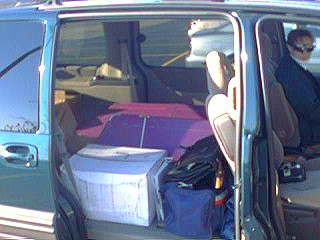
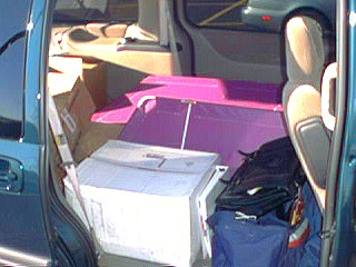
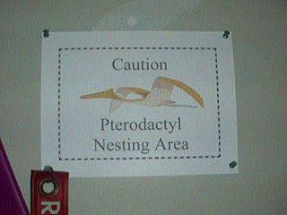
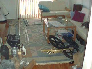
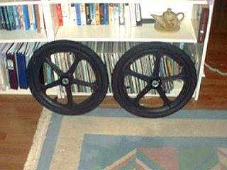
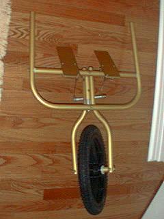
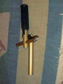
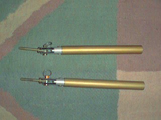
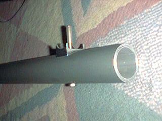
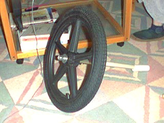
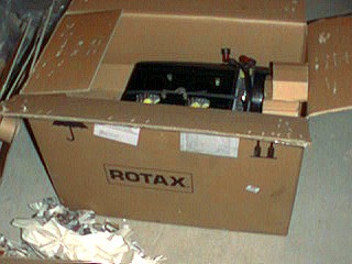
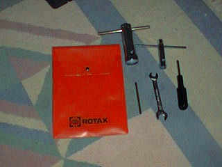
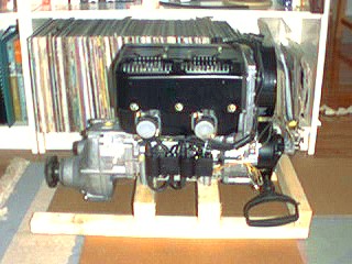
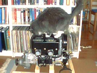
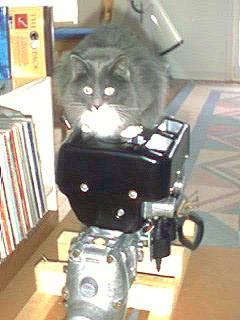
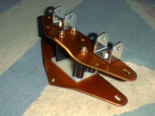
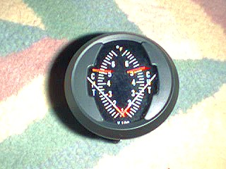
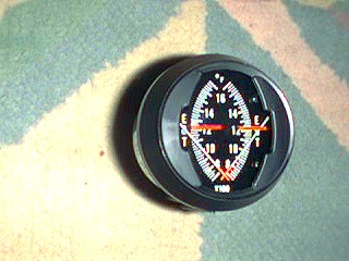
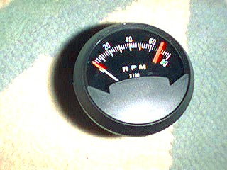
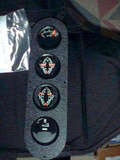
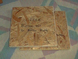
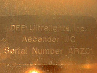
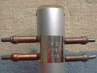
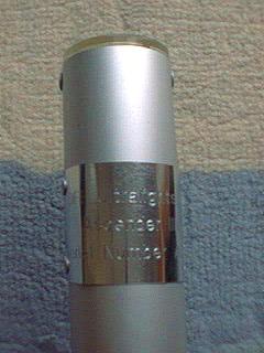
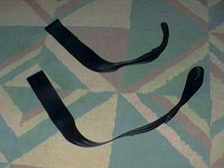
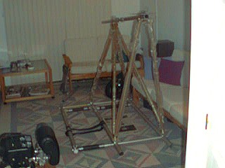
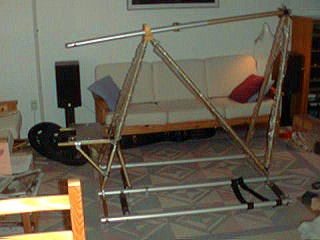
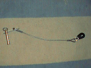
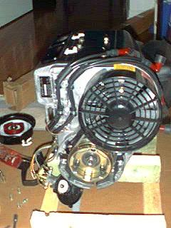
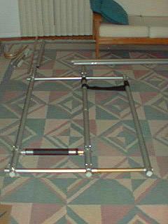
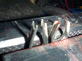
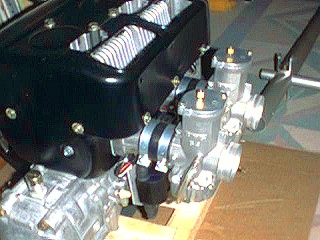
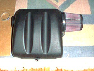
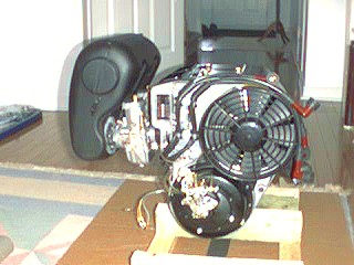
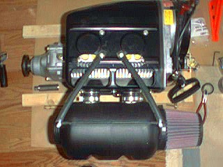
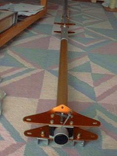
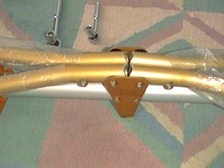
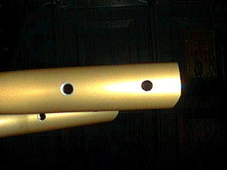
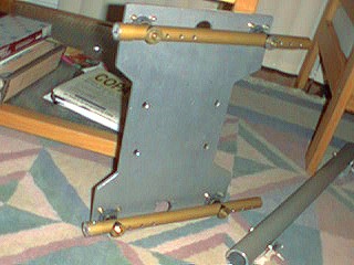
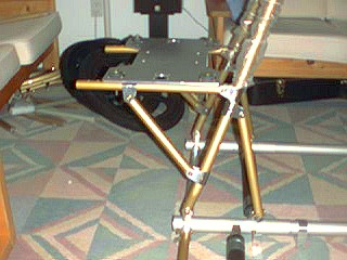
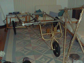
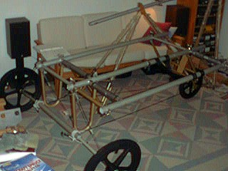
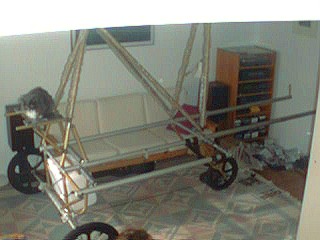
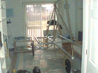
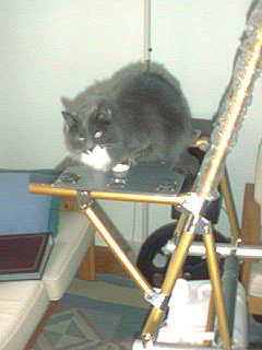
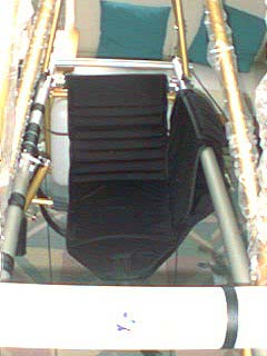
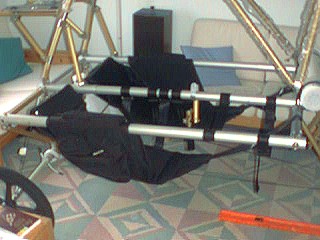
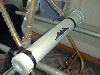
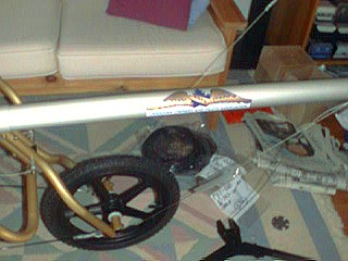
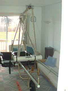
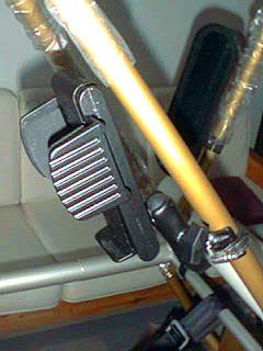
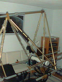
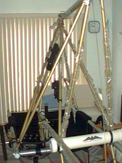
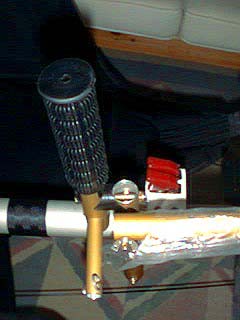
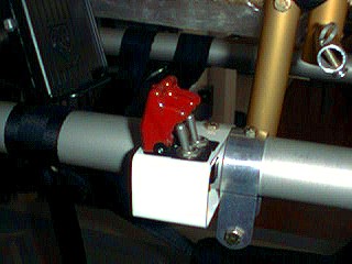
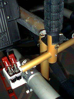
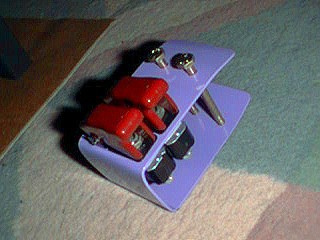
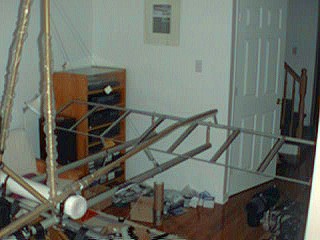
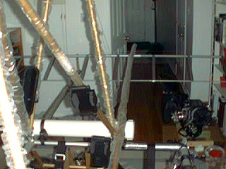
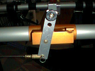
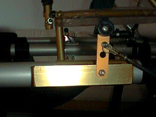
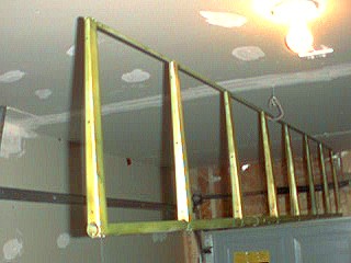
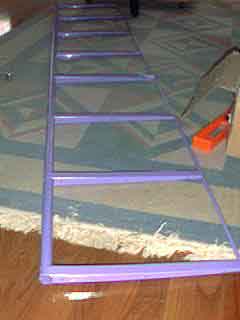
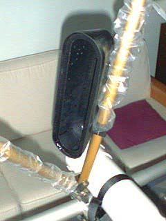
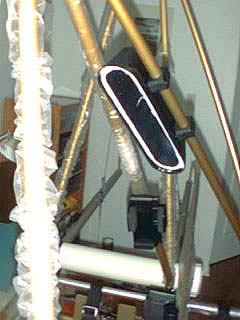
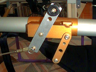
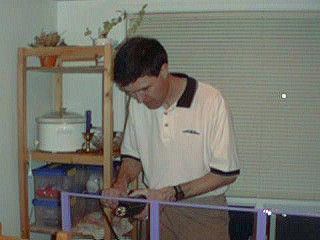
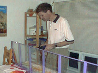
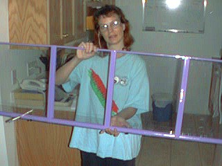
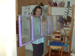
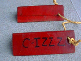
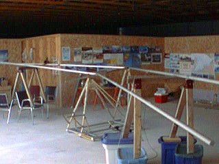
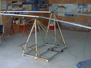
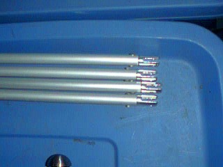
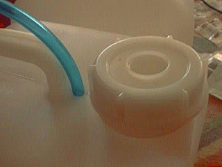
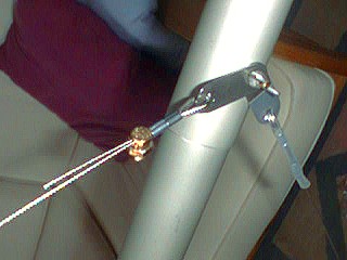
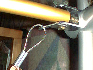
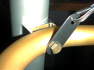
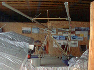
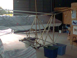
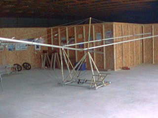
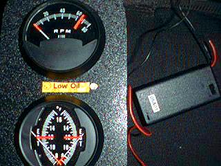
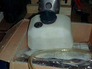
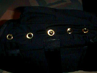
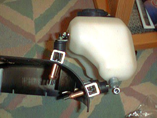
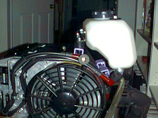
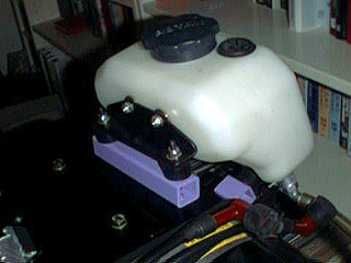
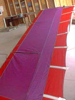
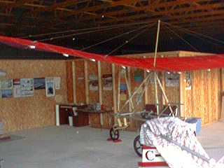
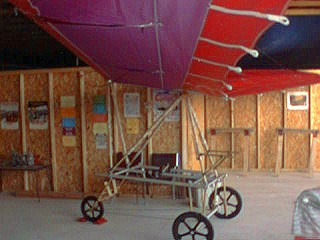
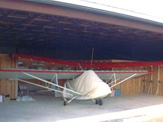
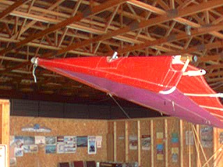
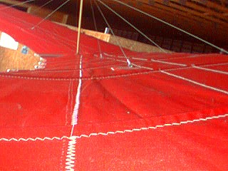
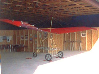
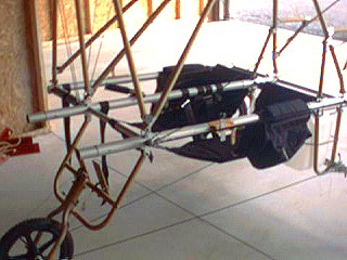
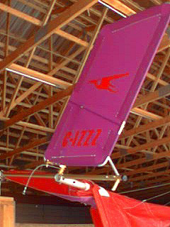
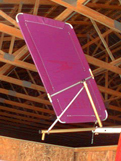
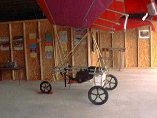
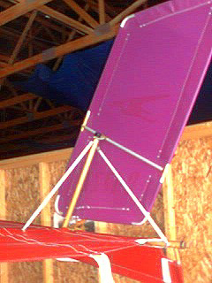
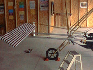
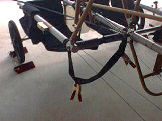
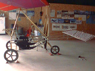
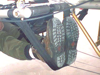
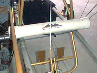
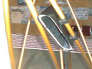
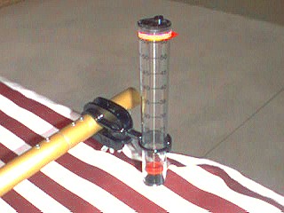
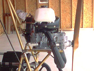
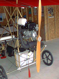
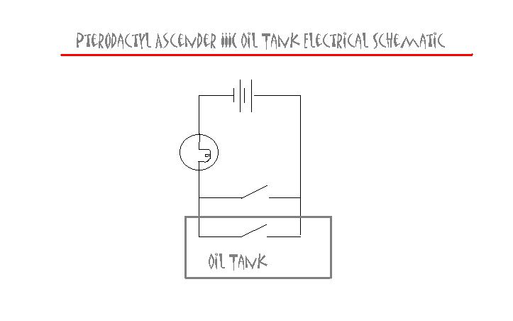
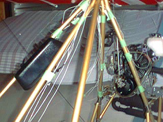
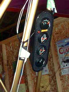
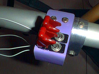
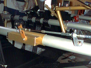
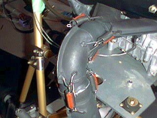
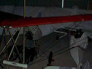
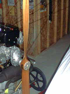
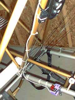
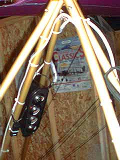
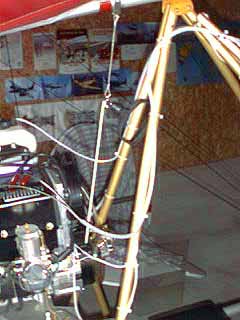
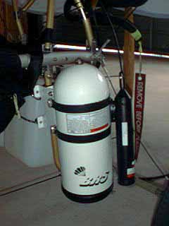
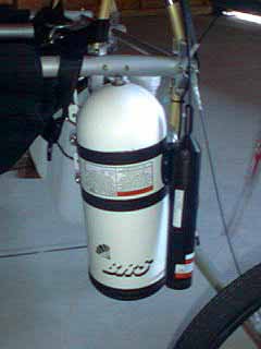
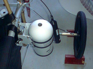
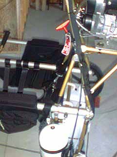
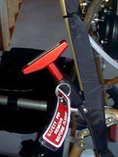
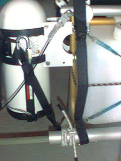
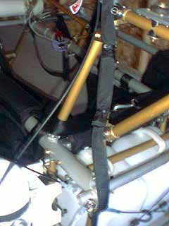
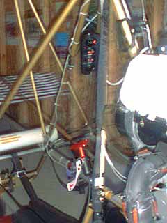
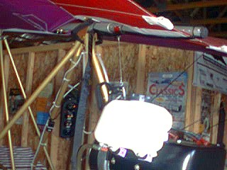
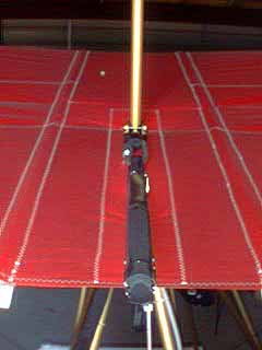
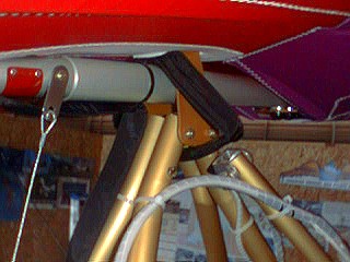
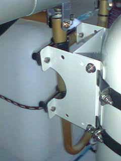
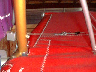
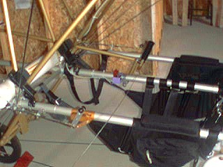
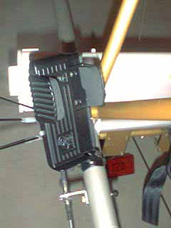
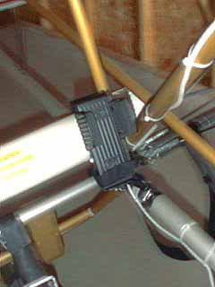
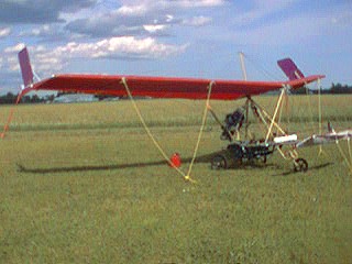
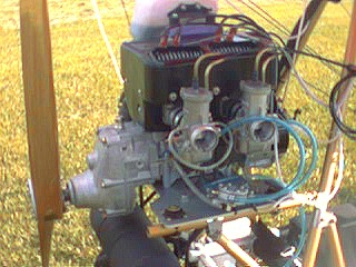
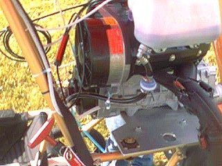
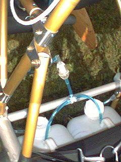
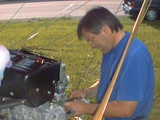
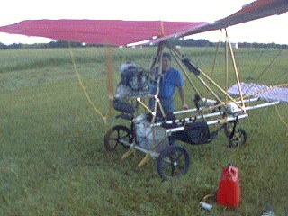
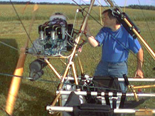
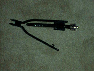
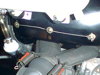
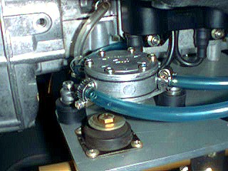
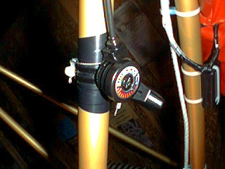
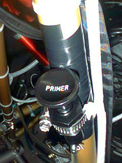
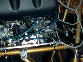
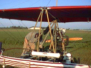
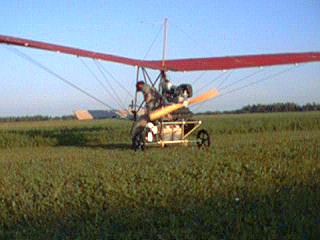
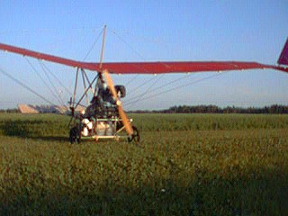
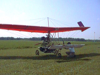
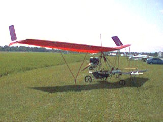
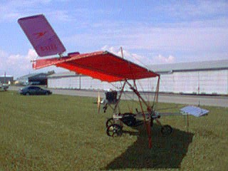
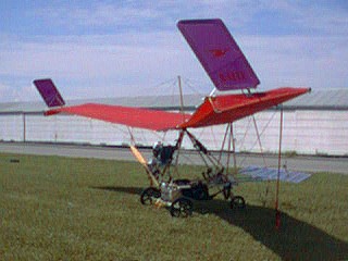
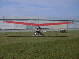
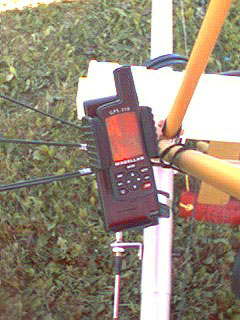
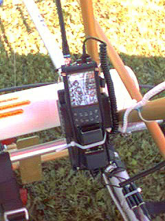
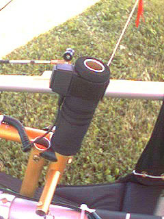
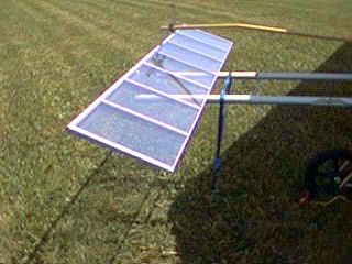
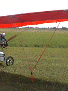
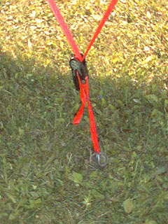
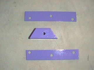
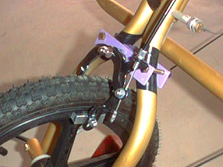
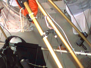