Photo Index
Here are all the photos that we have from our building process!
To save space and download times we have indexed them here in one place and hopefully in chronological order!
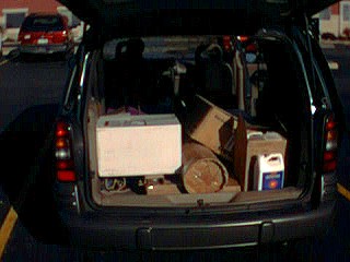
Going to get the kit at the Dac farm
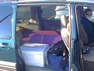
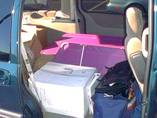
The whole Pterodactyl fits in a rented van with room to spare
On the road home with our plane Ruth is excited
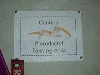
Sign of the times at our house
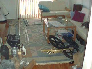
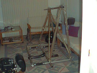
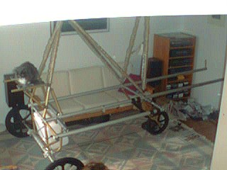
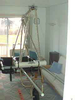
Can you actually build an airplane in your living room?
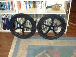
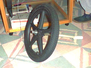
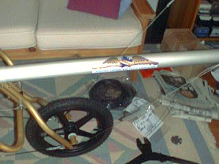
The main wheels are very decorative
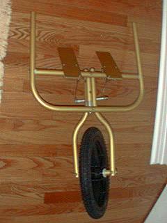
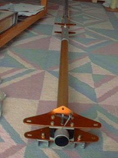
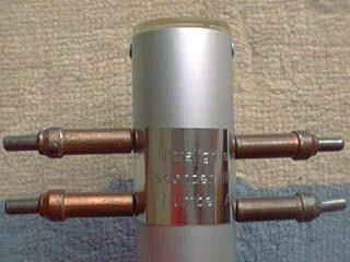
One of the first sub-projects was the DFE steerable nose gear
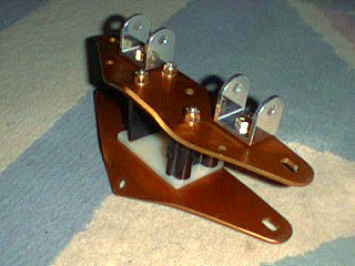
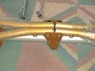
The nose plate assembly is a beautiful piece of sculpture
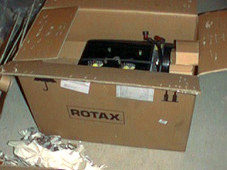
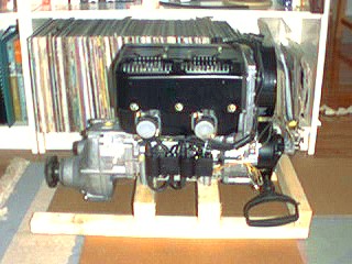
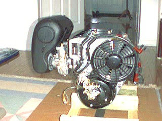
We took delivery of our very own Rotax 503 engine
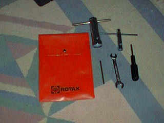
The engine comes with a nice little Rotax tool kit too!
The engine spent a lot of time in our living room during the building
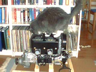
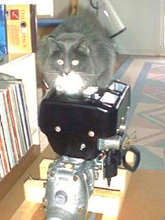
Our cat Zuby was curious about the engine
And then adopted it as her very own perch
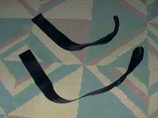
Some comforts were made up – these are co-pilot seat leg rest straps made from Lazair seat belts
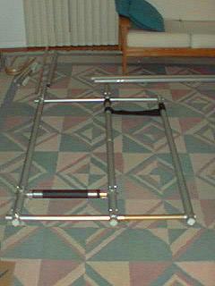
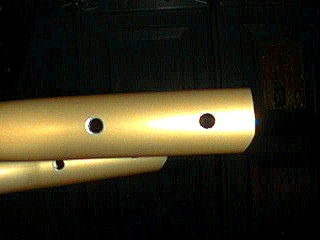
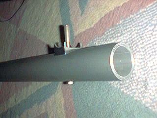
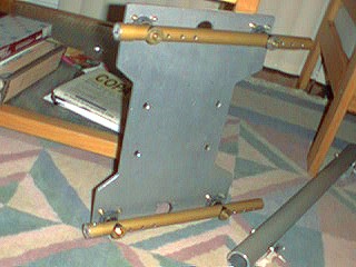
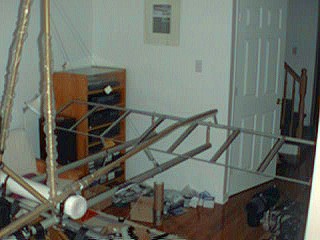
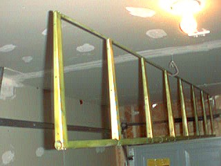
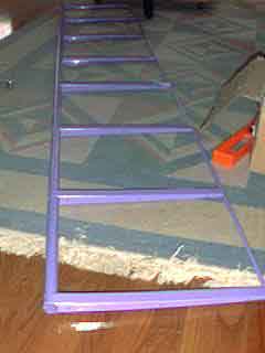
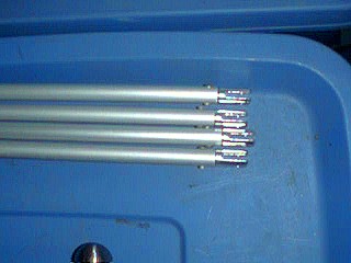
The first airframe tubes are laid out
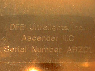
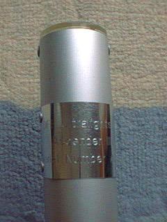
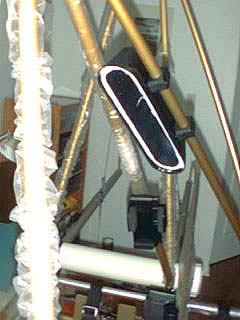
The data plate is engraved and ready for installation on the keel tube
The data plate is installed – Transport Canada will be happy!
Axles are fitted to the main wheels
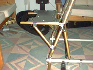
The engine mount ready for installation
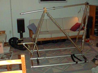
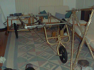
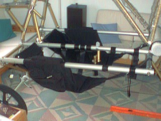
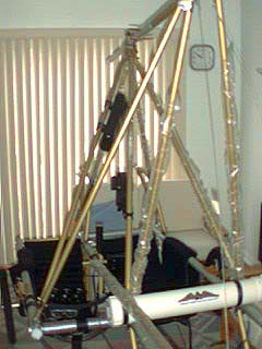
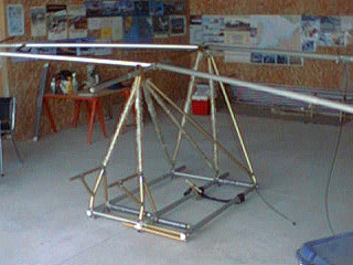
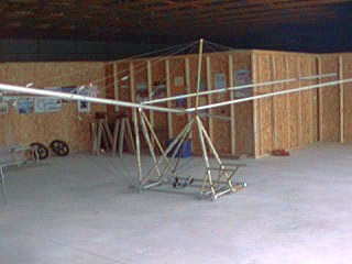
The airframe is on its wheels!
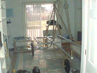
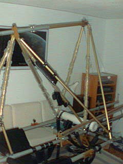
The living room is getting a bit small for the plane
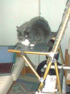
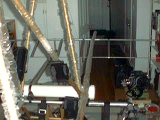
Airframe – Wheels, nose boom tubes and cat
Airframe - Zuby enjoyed the view
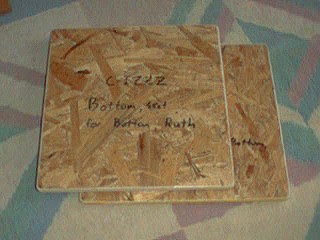
Home Depot provided the wood for the seat bottoms
The seats were installed for the first time
The RAM radio mount was trial-fitted
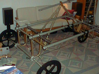
Airframe – Almost out of room in the living room!
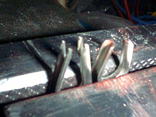
The cable thimbles all required modifications to remove the “tails” on them
Rigging cables – how could we do it without Kearney’s?
Our first swage was the pull start pulley
Installing nose boom cables and tangs
The instrument pod before the sealant is applied
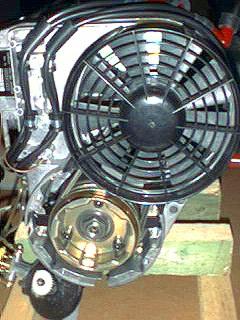
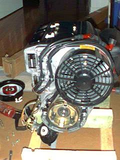
The Rotax 503 Engine – the fan system
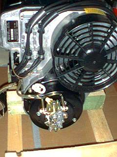
The Rotax 503 engine – re-orienting the starter
The Rotax 503 engine – starter reassembled in the right direction
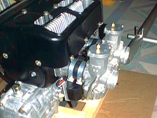
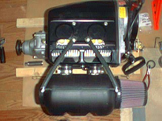
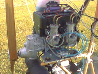
Engine work – the carburetors are installed
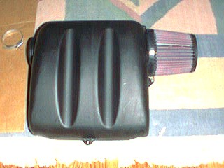
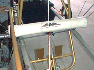
The Rotax 503’s intake silencer is test-fitted
The Rotax 503 intake silencer in place
Canard primed and ready for paint
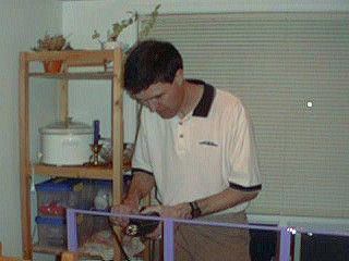
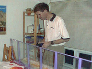
Adam working on the canard cover
Ruth shows off the finished canard
Ruth and the finished canard in the kitchen
Engine work – installing a custom choke lever for the remote chokes on the Rotax 503
Left hand (Pilot’s) Throttle installation
Right hand (Co-pilot’s) throttle installation
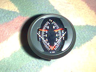
Engine instruments – the dual CHT
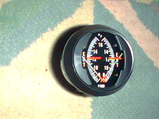
Engine instruments – the dual EGT
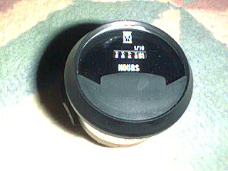
Engine instruments – the Hobbs meter to track engine hours
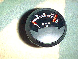
Engine instruments – the Tachometer
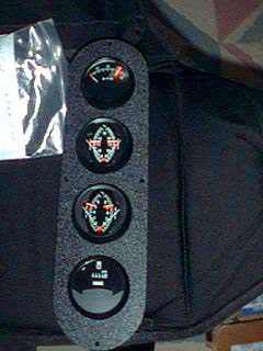
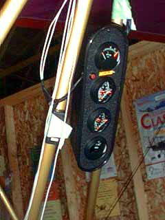
Engine instruments mounted on the panel
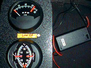
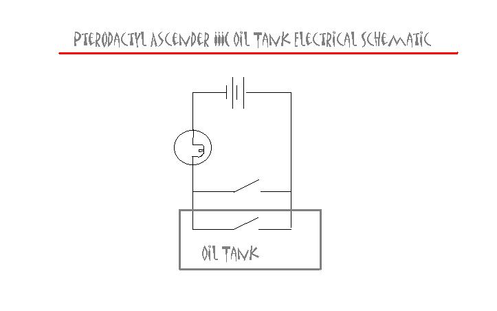
The low oil light warning system
New ignition switches test fitted
New ignition switches in the “off” position
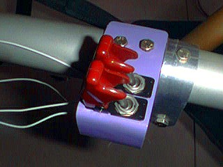
The new switches in the “off” position – guards “up”
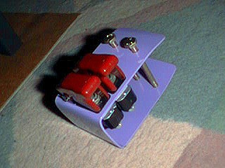
The wimpy ignition switches supplied were replaced with Mil Spec switches and a custom mount
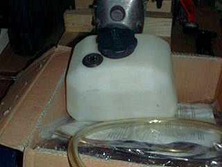
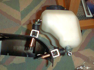
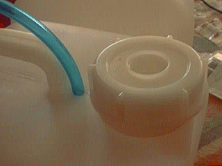
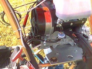
The Rotax 503 has oil injection and includes a 2 liter oil tank
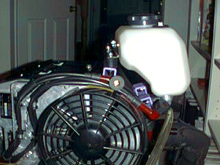
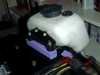
Oil injection tank mounting on the cowling
Oil tank mounting brackets were required to make it work
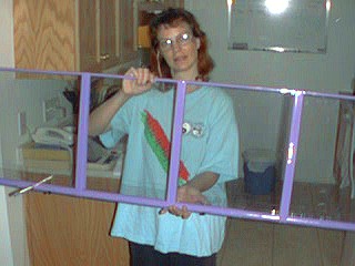
The winglet longitudinal and lateral braces were assembled
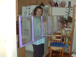
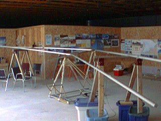
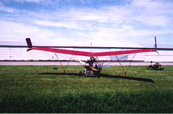
The wings were assembled at the hangar in Carp
The wings took a bit of time to rig up properly
Airframe – Rigging the wings in the hangar
Airframe – another rigging photo
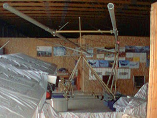
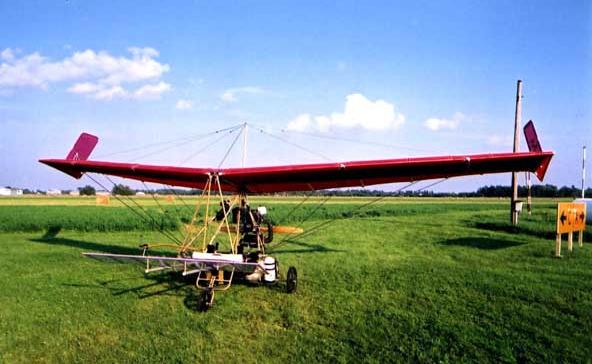
Airframe – almost done for now
Installing the fuel lines in the fuel tanks
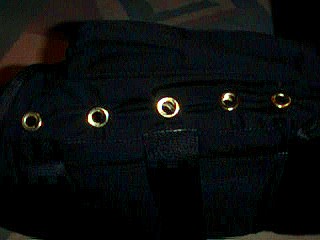
Seat modifications – grommets were installed to help the Velcro do its job
Working on the wing while it is upside-down
We even needed the chocks at last too
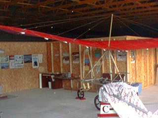
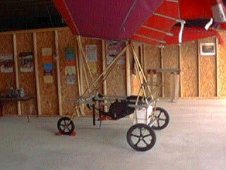
How a Challenger and the Pterodactyl fit together in one “T” hangar
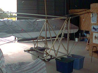
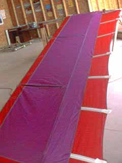
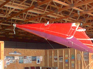
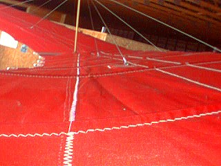
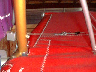
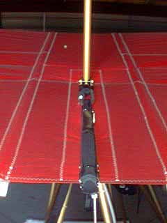
Top rigging done and close up of the sail
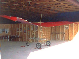
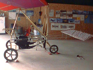
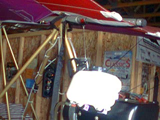
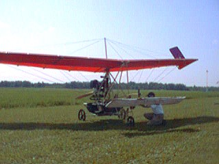
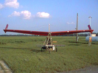
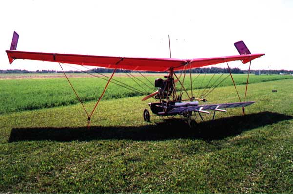
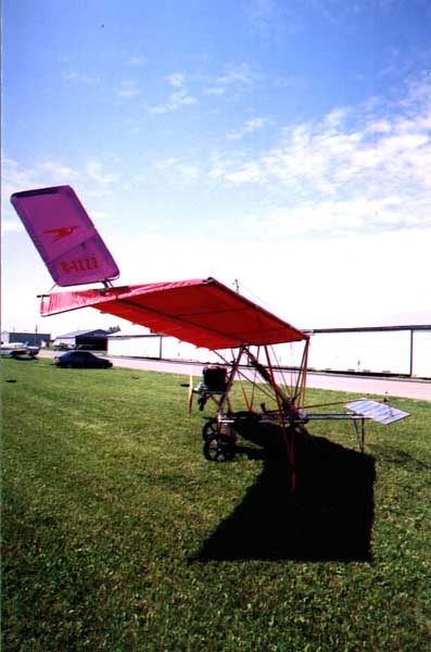
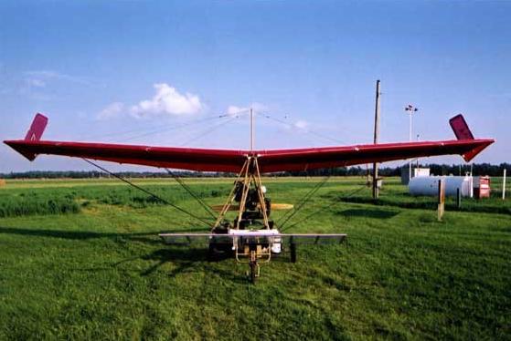
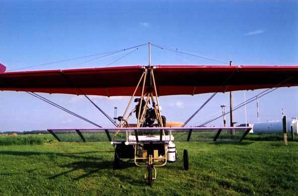
How it looks so far! – rigging in place and tips all installed
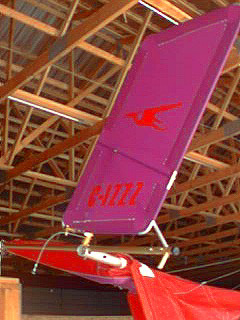
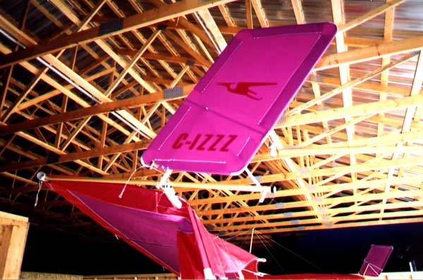
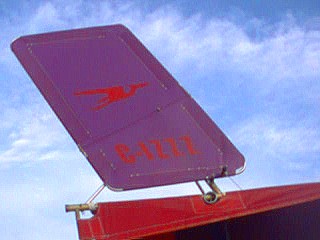
The left-hand winglet in place
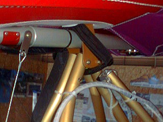
View of the inside of the winglet showing the longitudinal wing brace
Fuel tanks and seats installed
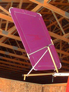
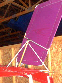
The winglet bracing is finished
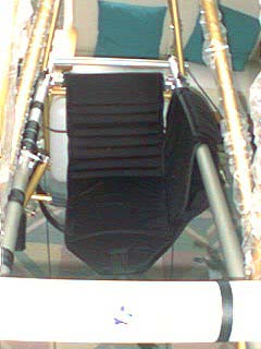
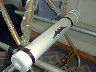
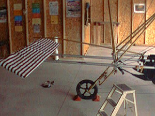
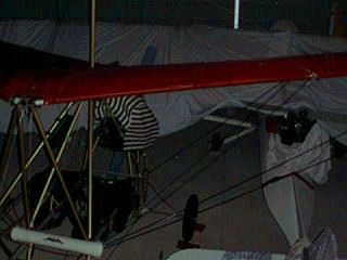
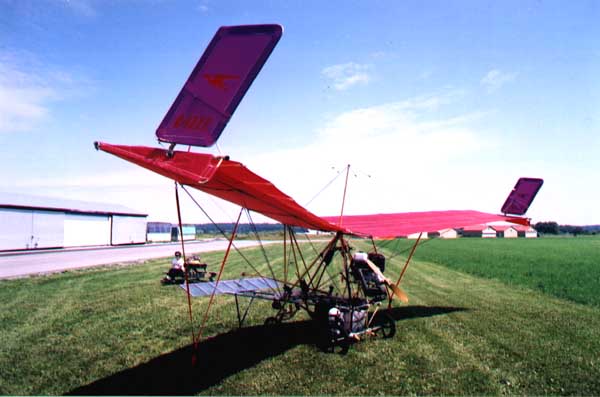
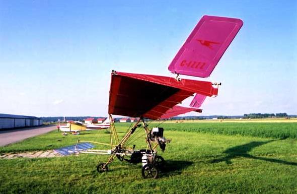
Canard installed and covered with a protective striped cover
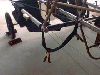
The co-pilot’s foot straps clamped in place
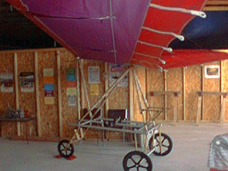
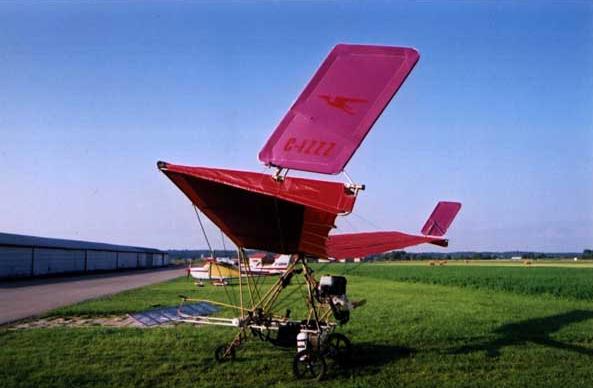
Overview with the canard installed
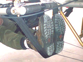
The co-pilot’s foot straps in their new configuration with Ruth’s boots
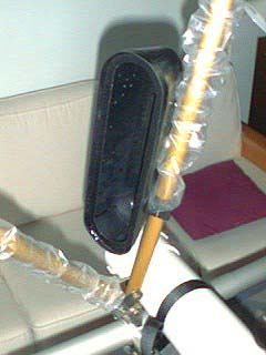
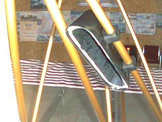
The instrument pod in position
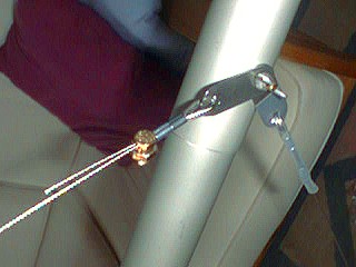
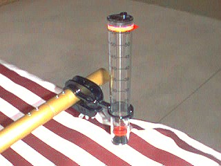
Hall Airspeed Indicator mounted on the canard actuating rod
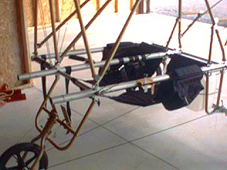
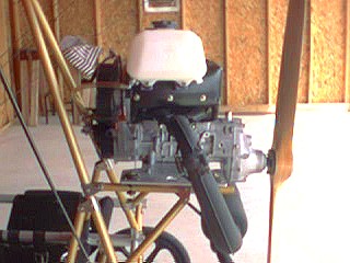
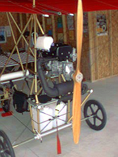
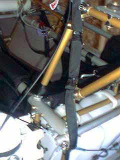
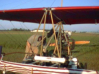
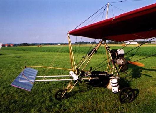
Rotax 503 in position – side view
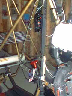
Rotax 503 in place with prop (temporarily) mounted – rear oblique view
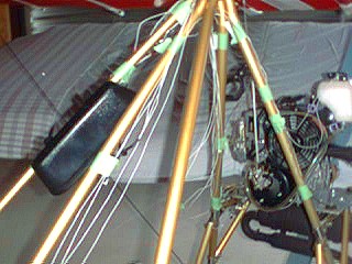
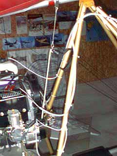
Wiring in place and held with green masking tape – for now
Instrument panel looking a bit more finished, too
Pilot’s throttle installed and ready for the main cable installation
Co-pilot’s throttle installed with the joining cable in place
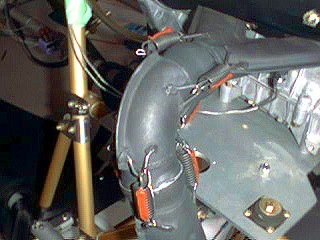
Exhaust system springs secured with lock wire and hi-temp RTV
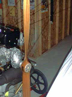
The prop is finished – torqued and tracked
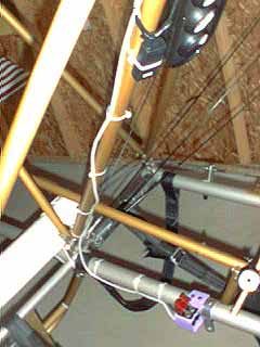
The ignition switch wires in place and spiral wrapped
Spiral wrapped wires run overhead to the instrument panel
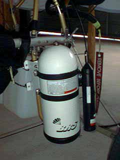
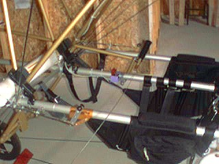
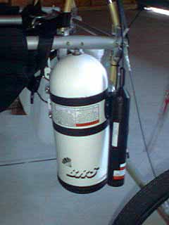
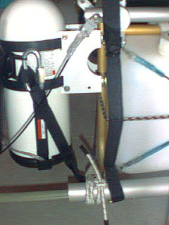
The BRS system installed – it goes on the left rear leg, pointing downwards
Detail of the winglet cable at the winglet end
The other end – the cable is connected to the control stick
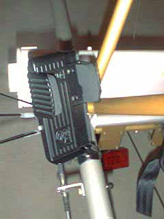
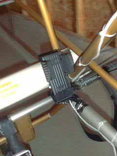
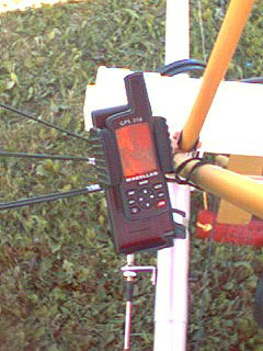
The RAM mount that will hold the GPS set
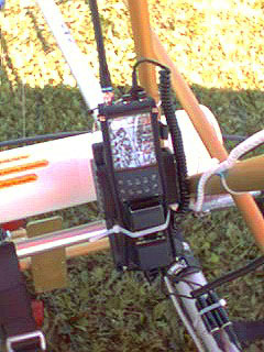
The RAM mount that will hold the radio
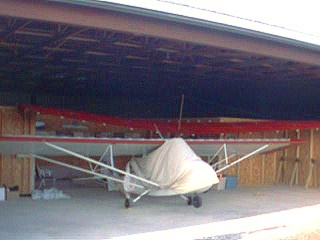
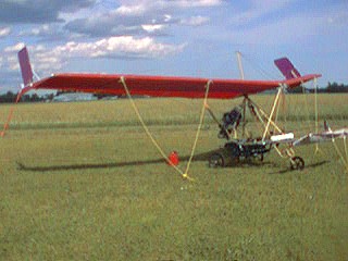
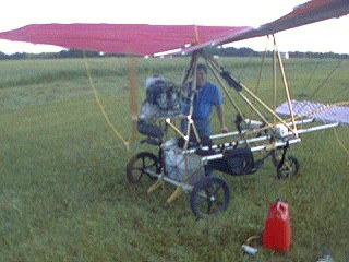
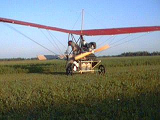
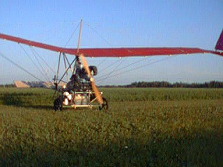
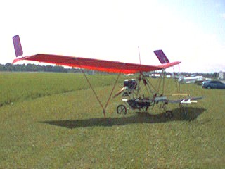
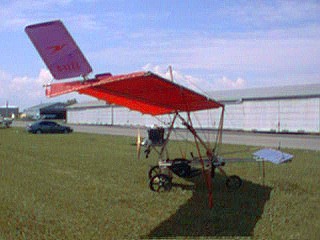
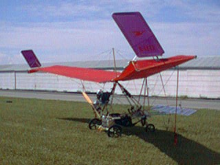
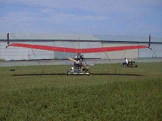
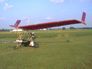
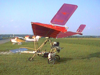
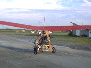
The plane outside for the first time – tied down and ready to ground run
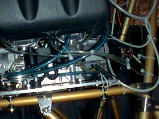
Carb installation and fuel lines installed too
Oil tank and oil filter installed
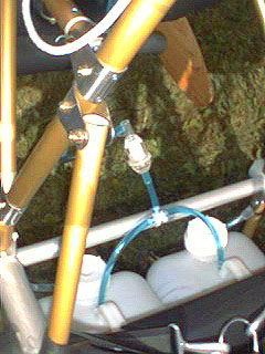
Fuel tank hoses installed with a Bosch filter
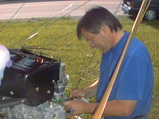
Daniel Sasseville makes an adjustment
The engine running and the prop turning
Doing a start – Daniel gets some exercise on the recoil starter
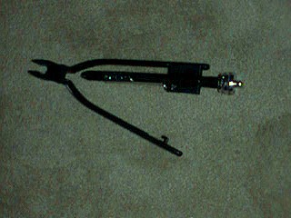
A nice thing to have in the toolbox – lockwire twisters
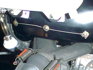
The result – lockwired AN500 A8-A screws. These should stay in place!
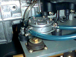
The new lord-mounted fuel pump on the engine deck location
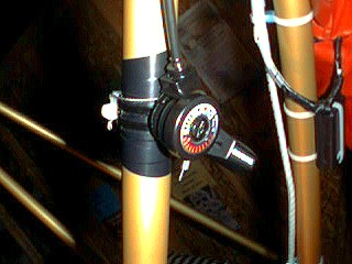
The choke actuator (by Shimano)
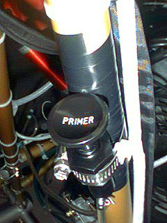
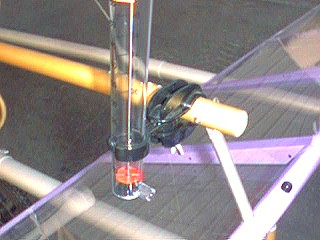
Primer installation on a strut tube – held in place with a hose clamp
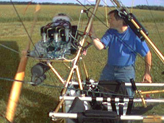
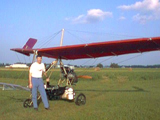
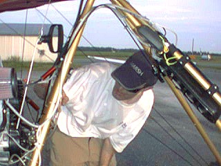
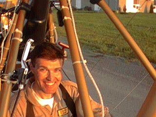
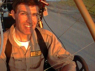
Adam gets ready to start the engine
Adam gets ready to do the ground runs
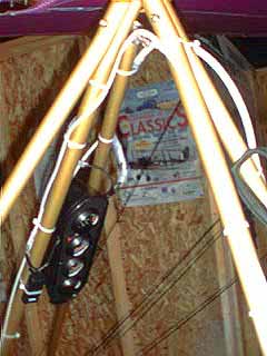
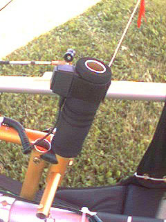
New stick grip with PTT switch installed
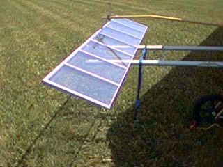
A look at the canard uncovered
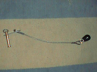
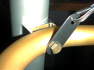
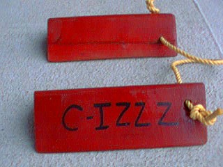
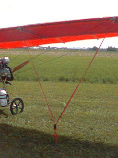
The unique tie down system I designed, using one ratchet and two connection points
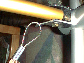
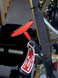
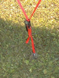
Anchor point detail at the corkscrew, showing the ratchet
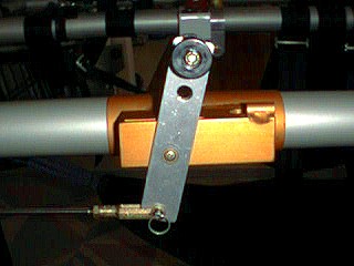
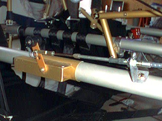
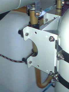
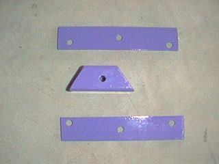
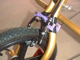
6061-T6 0.125” brackets and 1” square tube spacer
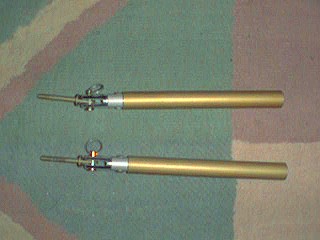
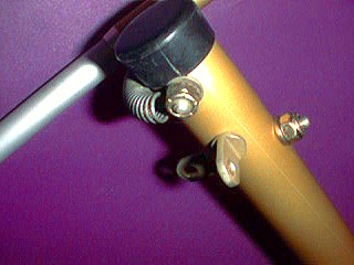
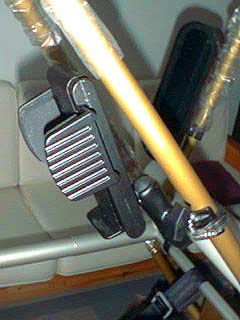
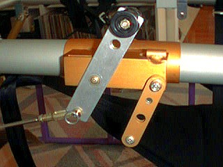
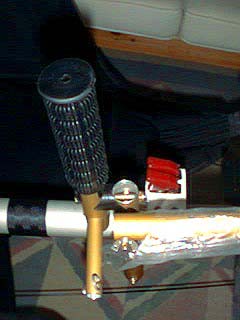
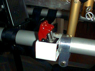
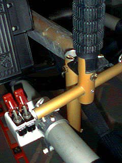
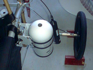
The brake assembly clamped onto the front SNG forks
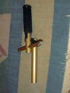
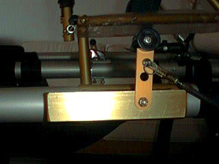
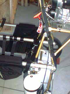
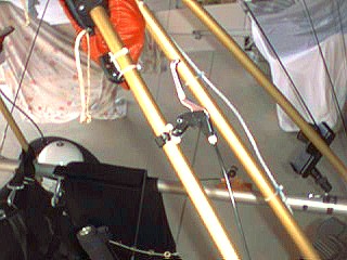
The hand control mounted on the 1” sidecar tube
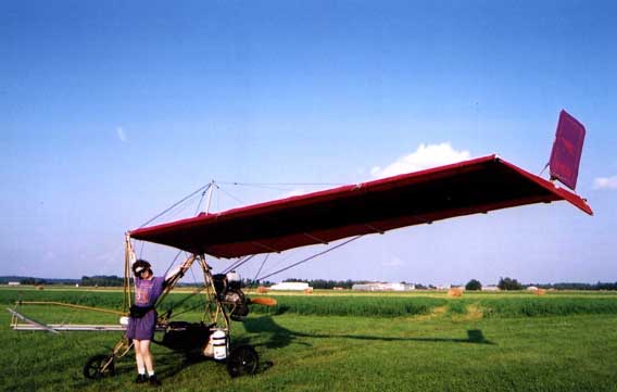
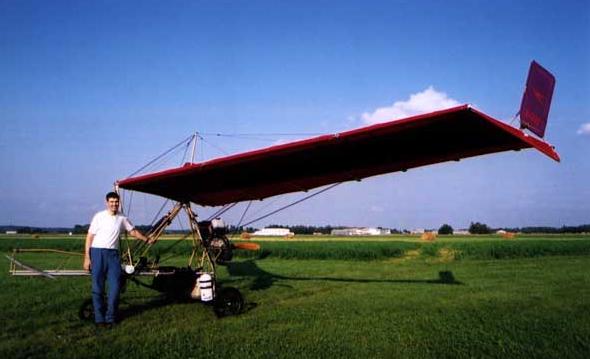
Our pre-flight photos:
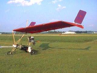
Our first flight photos:
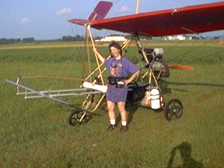
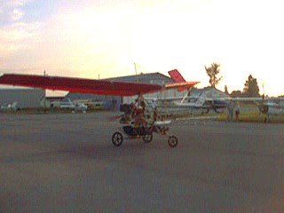
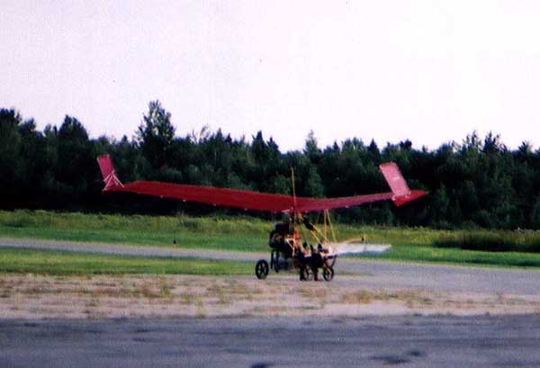
Flight completed taxiing back in
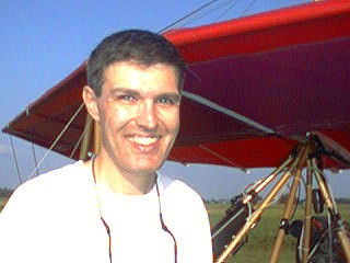
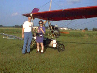
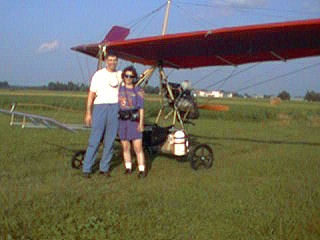
Happy to have the first flight completed!
Some other Miscellaneous pictures:
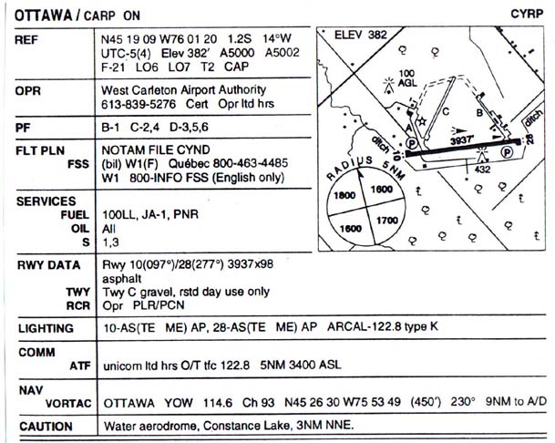
Our home airfield – CYRP Carp ON
The schematic diagram of the low oil warning system