
2- INFRARED RECEIVER
Infrared receiver circuit is designed to detect any kind of infrared signal and to change that signal into voltage. For this purpose we need infrared transducers. When a constant beam of infrared light is resident on the infrared transducer from the infrared transmitter or any kind of infrared source, the circuit will be virtually inactive.
To design the circuit which will give us the output as shown above, we have to study some basic principles of :
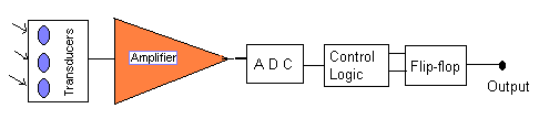
The basic block diagram of the receiver is given above :
We can see in the above diagram that when the IR strikes the Transducers, a very small voltage is produced which is then amplified and converted to digital by ADC (analogue to digital converters). The output of the ADC is fed into Control Logic which not only control the input and output of the flip-flop but also other circuits like computer buffer circuit.
Receiver Circuit Construction :
The Infrared receiver circuit uses all the previous mentioned information.
The circuit is discussed stage wise below :
In the first stage the three sensors are amplified so that the voltage of the sensors, which is usually in 100 - 400 mili-volts is amplified to a gain of 100, so as to make the voltage between 0-9 Volts (depending on the biasing voltage of the Op-Amp). Note here we are getting the output of an inverting Op-Amp. 0.01m F capacitors are used to ground the AC noise as shown in the diagram.
The second stage is to invert and at the same time convert all the Op-Amp outputs into Digital. Therefore we use comparators. The Positive terminal of the comparator is grounded and we input the signal to the negative terminal. Here no feed back is used. For example the voltage at the sensor is 50 mV when its in front of the IR transmitter. It is then amplified by the inverting Op-Amp to give us 1.5 V. This, when fed into the comparator will change it to 9 V. On the other hand if there does not exit any IR rays, then the sensor should show 0 V ideally, But however some IR noise is present in the light. Therefore the sensor will show 12mV. The amplifier will amplify it an d give us inverting output of 5 V. This When fed into the comparator will change it to 1.25 V. Thus we have two distinct voltages at the output of the comparator. The V maximum 9V is our logic 1 and the V minimum (1.25) is our logic 0.
The third stage is however not so important but if the flip-flop chip in the next stage uses CMOS logic then we feed our signal into a TTL NOT gates twice, to get our signal from 0 to 9 exactly.
This fourth stage uses self triggered flip-flop made up of four, three input NAND gates. Here it should be noted that we use J-K flip-flop for better results. The output is from Q, the input is fed at J and K is to clear the value of Q. When J is 9V for a second or less the flip-flop is switched on and Q = 1 . which mean now whatever the value of J the Q will remain at 1. Which means that we can use Q to trigger a 6V relay and attach an electronic alarm for the security system. We can only reset Q by K. If K is attached to a one pulse switch "S1" as shown, which is always grounded. To generate a pulse we press the switch to +9V and release it to be connected back to the ground.
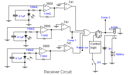
This will generate a pulse. If J = 0 then Q =0 which means that the relay will switch off the alarm. To design the IR receiver circuit we have to first carry out some experiments to know what components we need and how to design the receiver. These experiments are discussed in the next topic.
In the above figure (3.11) the biasing voltage of all OP-AMP �s is 9V. "Comp1" and "Comp2" are the inputs to the computer. "Comp 1" is the counter trigger. "Comp 2" is the for the bell. Control logic circuit is discussed in the following chapter. The relay that could be used here is of 6V and 0.02 A. If the size of the relay is large enough then we can use 220 V bell for this purpose. However here a very loud buzzer is used with extra batteries of 3V.