|
|
|
|
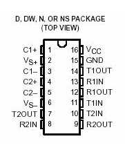
DUAL EIA-232 DRIVER/RECEIVER
|
- Operates
With Single 5-V Power Supply
- LinBiCMOS. Process Technology
- Two Drivers and Two Receivers
- 30-V Input Levels
- Low Supply Current . . . 8 mA Typical
- Meets or Exceeds TIA/EIA-232-F and ITU
Recommendation V.28
- Designed to be Interchangeable With
Maxim MAX232
- ESD Protection Exceeds JESD 22
2000-V Human-Body Model (A114-A)
- Applications
TIA/EIA-232-F
Battery-Powered Systems
Terminals
Modems
Computers
- Package Options Include Plastic
Small-Outline (D, DW, NS) Packages and
Standard Plastic (N) DIPs
|
Description
The MAX232 device is a dual driver/receiver that includes a capacitive
voltage generator to supply EIA-232 voltage levels from a single
5-V supply. Each receiver converts EIA-232 inputs to 5-V TTL/CMOS
levels. These receivers have a typical threshold of 1.3 V and a
typical hysteresis of 0.5 V, and can accept .30-V inputs. Each driver
converts TTL/CMOS input levels into EIA-232 levels. The driver,
receiver, and voltage-generator functions are available as cells
in the Texas Instruments LinASIC. library.
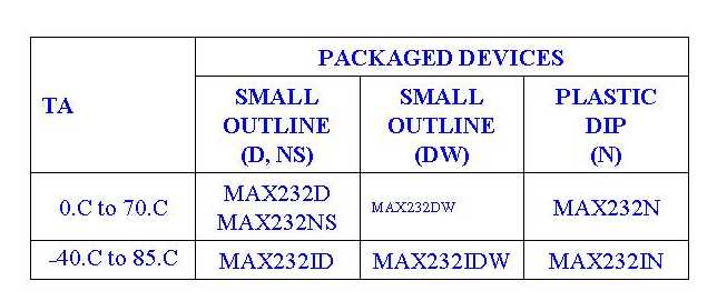
The MAX232 is characterized for operation from 0.C to 70.C. The
MAX232I is characterized for operation from -40.C to 85.C.
|
|
The D and DW packages are available taped and reeled by adding
an R to the part number
(i.e., MAX232DR). The NS package is only available taped and reeled.
|
|
PARAMETER MEASUREMENT
INFORMATION
|
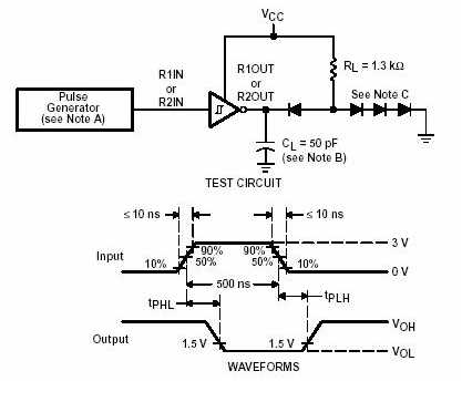
NOTES: A. The pulse generator has the following characteristics:
ZO = 50 ., duty cycle . 50%.
B. CL includes probe and jig capacitance.
C. All diodes are 1N3064 or equivalent.
Figure 1. Receiver Test Circuit and Waveforms for tPHL and tPLH
Measurements
|
|
PARAMETER MEASUREMENT
INFORMATION
|
|
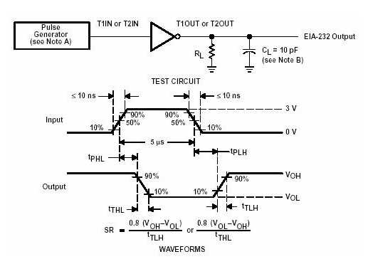
NOTES: A. The pulse generator has the following characteristics:
ZO = 50 ., duty cycle . 50%.
B. CL includes probe and jig capacitance.
Figure 2. Driver Test Circuit and Waveforms for tPHL and tPLH
Measurements (5-.s input)
|
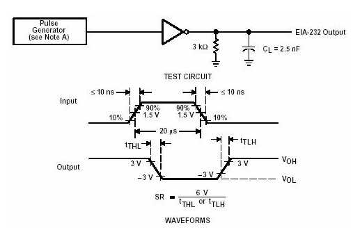
NOTE A: The pulse generator has the following characteristics: ZO
= 50 ., duty cycle . 50%.
Figure 3. Test Circuit and Waveforms for tTHL and tTLH Measurements
(20-.s input)
|
|
APPLICATION INFORMATION
|
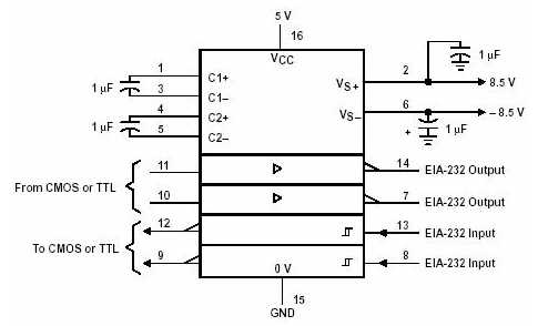
Figure 4. Typical Operating
Circuit
|
|
|
|
|